Isuzu D-Max / Isuzu Rodeo (TFR/TFS). Manual — part 53
4JA1-TC/4JH1-TC ENGINE DRIVEABILITY AND EMISSIONS
6E–207
Diagnostic Trouble Code (DTC) P0560 (Symptom Code A) (Flash Code 35)
System Voltage Malfunction (PSG)
Step
Action
Value(s)
Yes
No
1
Was the “On-Board Diagnostic (OBD) System Check”
performed?
—
Go to Step 2
Go to On Board
Diagnostic
(OBD) System
Check
2
1. Connect the Tech 2.
2. Review and record the failure information.
3. Select “F0: Read DTC Infor As Stored By ECU” in
“F0: Diagnostic Trouble Codes”.
Is the DTC P0560 (Symptom Code A) stored as
“Present Failure”?
—
Go to Step 3
Refer to
Diagnostic Aids
and Go to Step
3
3
1. Using the Tech 2, ignition “On” and engine “Off”.
2. Select “F1: Clear DTC Information” in “F0:
Diagnostic Trouble Codes” with the Tech 2 and
clear the DTC information.
3. Operate the vehicle and monitor the “F0: Read
DTC Infor As Stored By ECU” in the “F0:
Diagnostic Trouble Codes”.
Was the DTC P0560 (Symptom Code A) stored in this
ignition cycle?
—
Go to Step 4
Refer to
Diagnostic Aids
and Go to Step
4
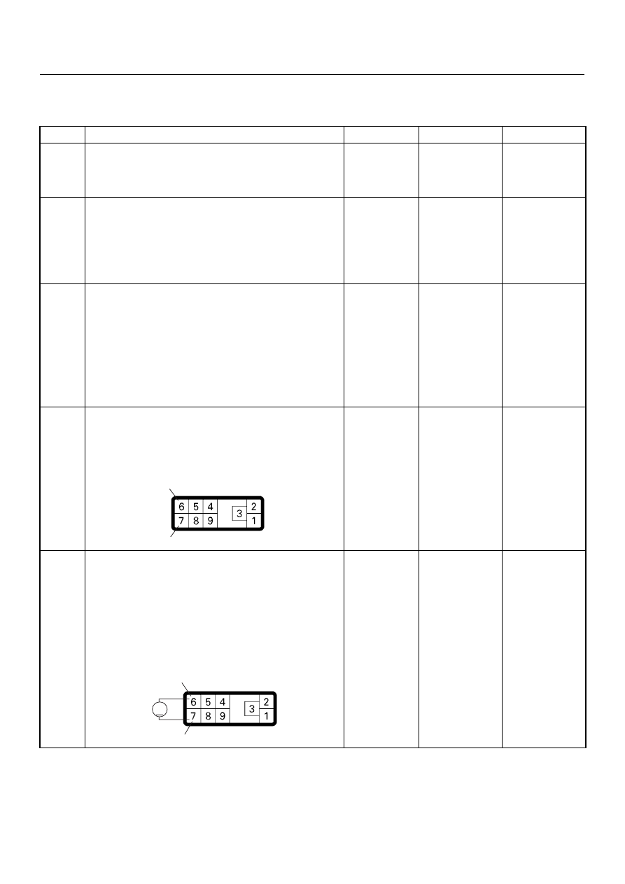
4
Check for poor/faulty connection at the PSG (pump
control unit) connector. If a poor/faulty connection is
found, repair as necessary.
Was the problem found?
—
Verify repair
Go to Step 5
5
Using the DVM and check the PSG (pump control
unit) power supply circuit.
1. Ignition “On”, engine “Off”.
2. Disconnect the PSG (pump control unit)
connector.
3. Check the PSG (pump control unit) power supply
circuit.
Was the DVM indicated specified value?
10 - 14V
Go to Step 7
Go to Step 6
6
7
E-6
6
7
V
E-6

6E–208
4JA1-TC/4JH1-TC ENGINE DRIVEABILITY AND EMISSIONS
6
Check for poor/faulty connection of the PSG (pump
control unit) ground at the cylinder body. If a poor/
faulty connection is found, repair as necessary.
Was the problem found?
—
Verify repair
Go to Step 7
7
Replace the injection pump assembly.
Is the action complete?
—
Verify repair
—
Step
Action
Value(s)
Yes
No
E-10
4JA1-TC/4JH1-TC ENGINE DRIVEABILITY AND EMISSIONS
6E–209
DIAGNOSTIC TROUBLE CODE (DTC) P0561 (SYMPTOM CODE A)
(FLASH CODE 18) SYSTEM VOLTAGE CIRCUIT MALFUNCTION
DIAGNOSTIC TROUBLE CODE (DTC) P0561 (SYMPTOM CODE B)
(FLASH CODE 18) SYSTEM VOLTAGE CIRCUIT MALFUNCTION
Condition for setting the DTC and action taken when the DTC sets
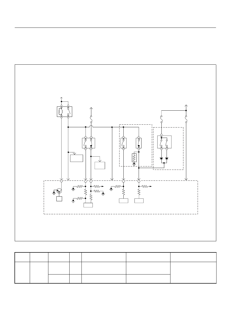
Circuit Description
The ECM monitors the ignition switch signal on the feed
terminal to the ECM. If the ignition switch signal with
malfunction, DTC P0561 (Symptom Code A) or DTC
P0561 (Symptom Code B) will be stored.
Diagnostic Aids
An intermittent may be caused by the following:
Flash
Code
Code
Symptom
Code
MIL
DTC Name
DTC Setting Condition
Fail-Safe (Back Up)
18
P0561
A
OFF
System Voltage Circuit Mal-
function
The ECM recognized ignition
switch turn off signal during
ECM is activated.
ECM stops engine.
B
ON
System Voltage Circuit Mal-
function
Ignition switch circuit is mal-
function.
Battery
Voltage
Battery
Voltage
ECM
Main Relay
Stop
Light
10A
Injection
Pump
Stop
Lamp
IC
IC
CPU
0.5
BLU/
BLK
58
2.0
BLU/
RED
0.5
BLU/
RED
3
0.5
WHT/
BLK
65
0.85
RED
0.85
RED
0.85
GRN
30
0.5
BLU/
RED
63
0.5
YEL
31
0.5
RED/
BLK
0.5
BLU/
RED
0.5
BLU/
RED
0.85
WHT
0.5
WHT/
RED
0.5
RED/
GRN
Clutch
SW
Resister
Neutral
SW
87
0.5
BLU/
YEL
39
Brake
SW
M/T
A/T
Inhibitor
SW
Ignition
SW
Back,
Turn
15A
Engine
15A
µP
N
P
Engine
Control
Module
(ECM)
Batt
Batt

6E–210
4JA1-TC/4JH1-TC ENGINE DRIVEABILITY AND EMISSIONS
• Poor connections.
• Misrouted harness.
• Rubbed through wire insulation.
• Broken wire inside the insulation.
Check for the following conditions:
• Poor connection at ECM-Inspect harness connectors
for backed out terminals, improper mating, broken
locks, improperly formed or damaged terminals, and
poor terminal to wire connection.
• Damaged harness-Inspect the wiring harness for
damage. If the harness appears to be OK, observe
the “Ignition Status” display on the Tech2 while
moving connectors and wiring harness related to the
sensor.
Diagnostic Trouble Code (DTC) P0561 (Symptom Code A) (Flash Code 18)
System Voltage Circuit Malfunction
Diagnostic Trouble Code (DTC) P0561 (Symptom Code B) (Flash Code 18)
System Voltage Circuit Malfunction
Step
Action
Value(s)
Yes
No
1
Was the “On-Board Diagnostic (OBD) System Check”
performed?
—
Go to Step 2
Go to On Board
Diagnostic
(OBD) System
Check
2
1. Connect the Tech 2.
2. Review and record the failure information.
3. Select “F0: Read DTC Infor As Stored By ECU” in
“F0: Diagnostic Trouble Codes”.
Is the DTC P0561 (Symptom Code A) or P0561
(Symptom Code B) stored as “Present Failure”?
—
Go to Step 3
Refer to
Diagnostic Aids
and Go to Step
3
3
1. Using the Tech 2, ignition “On” and engine “Off”.
2. Select “F1: Clear DTC Information” in “F0:
Diagnostic Trouble Codes” with the Tech 2 and
clear the DTC information.
3. Operate the vehicle and monitor the “F0: Read
DTC Infor As Stored By ECU” in the “F0:
Diagnostic Trouble Codes”.
Was the DTC P0561 (Symptom Code A) or P0561
(Symptom Code B)stored in this ignition cycle?
—
Go to Step 4
Refer to
Diagnostic Aids
and Go to Step
4
4
Check the “Engine-2” fuse (10A).
If the fuse is burnt out, repair as necessary.
Was the problem found?
—
Verify repair
Go to Step 5
Нет комментариевНе стесняйтесь поделиться с нами вашим ценным мнением.
Текст