Isuzu D-Max / Isuzu Rodeo (TFR/TFS). Manual — part 1309
8–156 ELECTRICAL-BODY AND CHASSIS
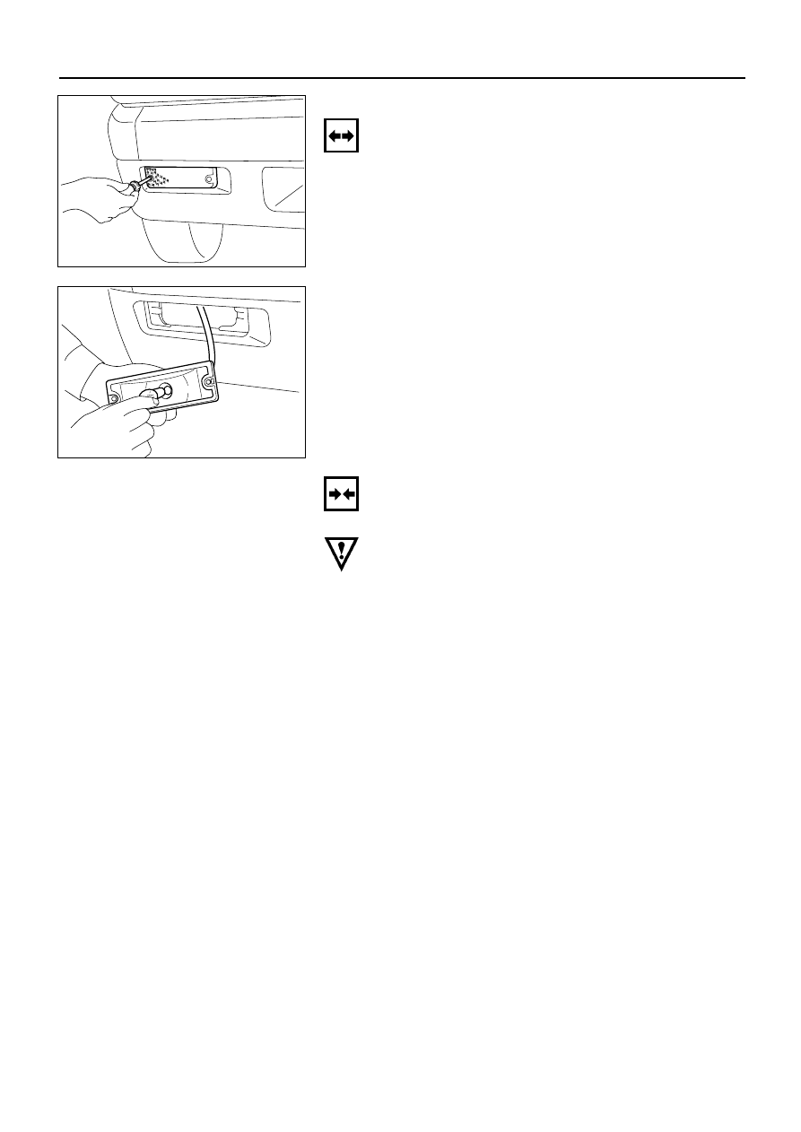
FRONT TURN LIGHT
Removal
1. Remove the front turn light lens.
2. Pull the light housing free.
D08RV862
3. Push the bulb in and turn it counterclockwise to
remove it from the light housing.
D08RV863
Installation
Follow the removal procedure in the reverse order to
install the front turn light.
Pay close attention to the important points mentioned in
the following paragraphs.
Bulb
Be absolutely sure that the front turn light bulb is
correctly installed.
This will prevent a poor contact and an open circuit.
ELECTRICAL-BODY AND CHASSIS 8–157
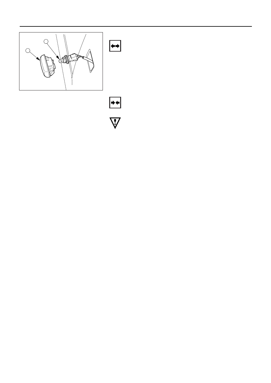
SIDE TURN LIGHT
Removal
1. Remove the lens 1.
•
Pull the light/bulb toward you while pushing the
light housing in the rear direction of the vehicle to
release its lock.
•
Remove the socket by turning it counterclockwise.
2. Pull the bulb 2 to remove it.
2
1
D08RV750
Installation
Follow the removal procedure in the reverse order to
install the side turn light.
Pay close attention to the important points mentioned in
the following paragraphs.
Bulb
Be absolutely sure that the side turn light bulb is correctly
installed.
This will prevent a poor contact and an open circuit.
8–158 ELECTRICAL-BODY AND CHASSIS
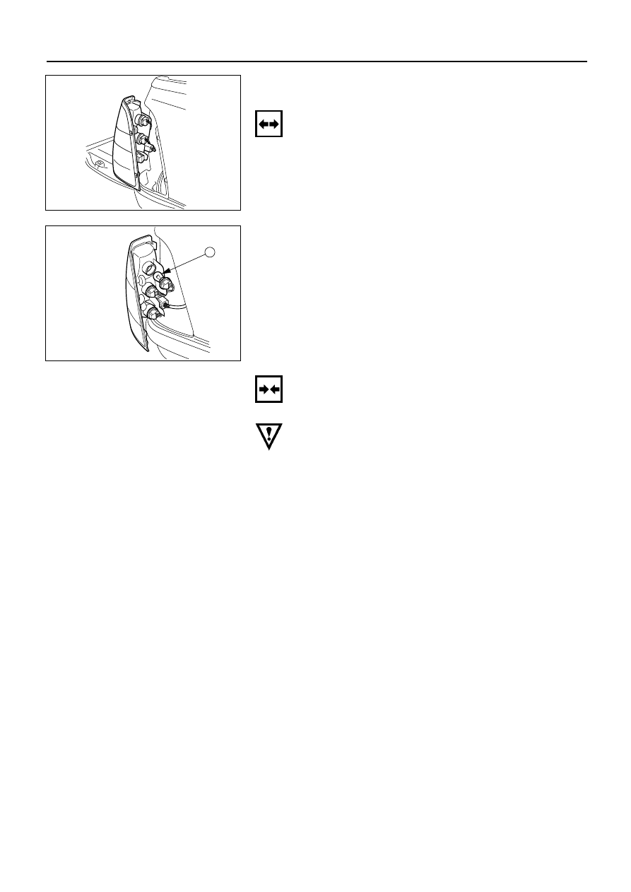
REAR COMBINATION LIGHT
Turn Signal Light
Removal
1. Open the rear gate.
2. Remove the screws.
3. Remove the rear combination light assembly.
D08RV751
4. Turn the bulb 1 counterclockwise to remove it.
1
D08RV752
Installation
Follow the removal procedure in the reverse order to
install the rear combination light.
Pay close attention to the important points mentioned in
the following paragraphs.
Bulb
Be absolutely sure that the rear combination light bulb is
correctly installed.
This will prevent a poor contact and an open circuit.
ELECTRICAL-BODY AND CHASSIS 8–159
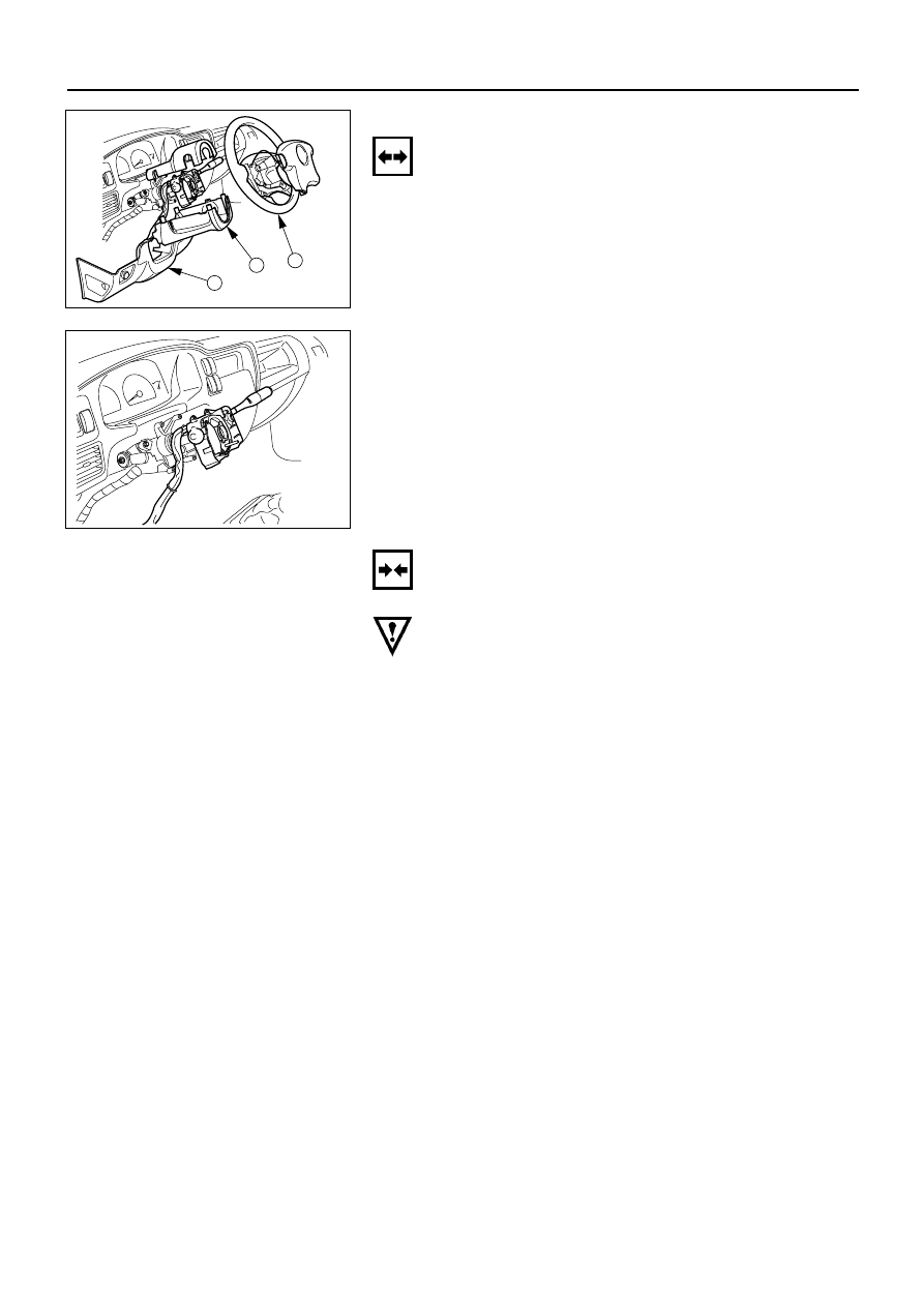
TURN SIGNAL SWITCH
Removal
1. Remove the steering wheel 1.
Refer to the “STEERING” Section of this Manual.
2. Remove the instruments panel lower cover 2.
3. Remove the steering column cover 3.
1
3
2
D08RV888
4. Disconnect the connector.
5. Remove the turn signal switch from the steering
shaft.
D08RV747
Installation
Follow the removal procedure in the reverse order to
install the turn signal switch (lever).
Pay close attention to the important points mentioned in
the following paragraphs.
Connector
Be absolutely sure that the turn signal switch connector is
securely connected.
This will prevent a poor contact and at an open circuit.
Нет комментариевНе стесняйтесь поделиться с нами вашим ценным мнением.
Текст