Isuzu D-Max / Isuzu Rodeo (TFR/TFS). Manual — part 1753
DIAGNOSIS 7A2-63
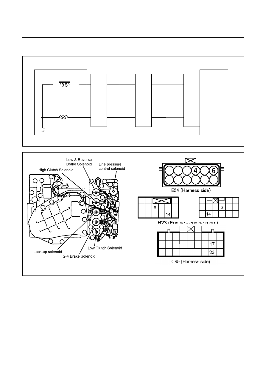
DTC P1860 (Flash Code 36) Lock-up Duty Solenoid Failure
Control Valve
TCM
B17
B23
B
Lock-up Solenoid
Terminal
Assembly
V
Line Pressure Solenoid
E54
(4)
(6)
H23
(14)
(6)
C95
(17)
(23)
B
V
Setting Condition:
•
The lock-up duty solenoid signal is open circuit or short circuit.
(The voltage different from the output ON/OFF signals was detected while the TCM monitors the solenoid output
voltage.)
Fail Safe:
•
The lock-up is inhibited.
Possible Cause:
•
Lock-up duty solenoid malfunction.
•
Open (Off) circuit or short (On) circuit of the lock-up duty solenoid.
7A2-64 DIAGNOSIS
•
Open circuit, short circuit to battery or short circuit to ground between lock-up duty solenoid terminal 4 and TCM
terminal B17 (C95).
•
Insufficient ground condition of the lock-up duty solenoid.
•
Poor connection of each connector.
Reference:
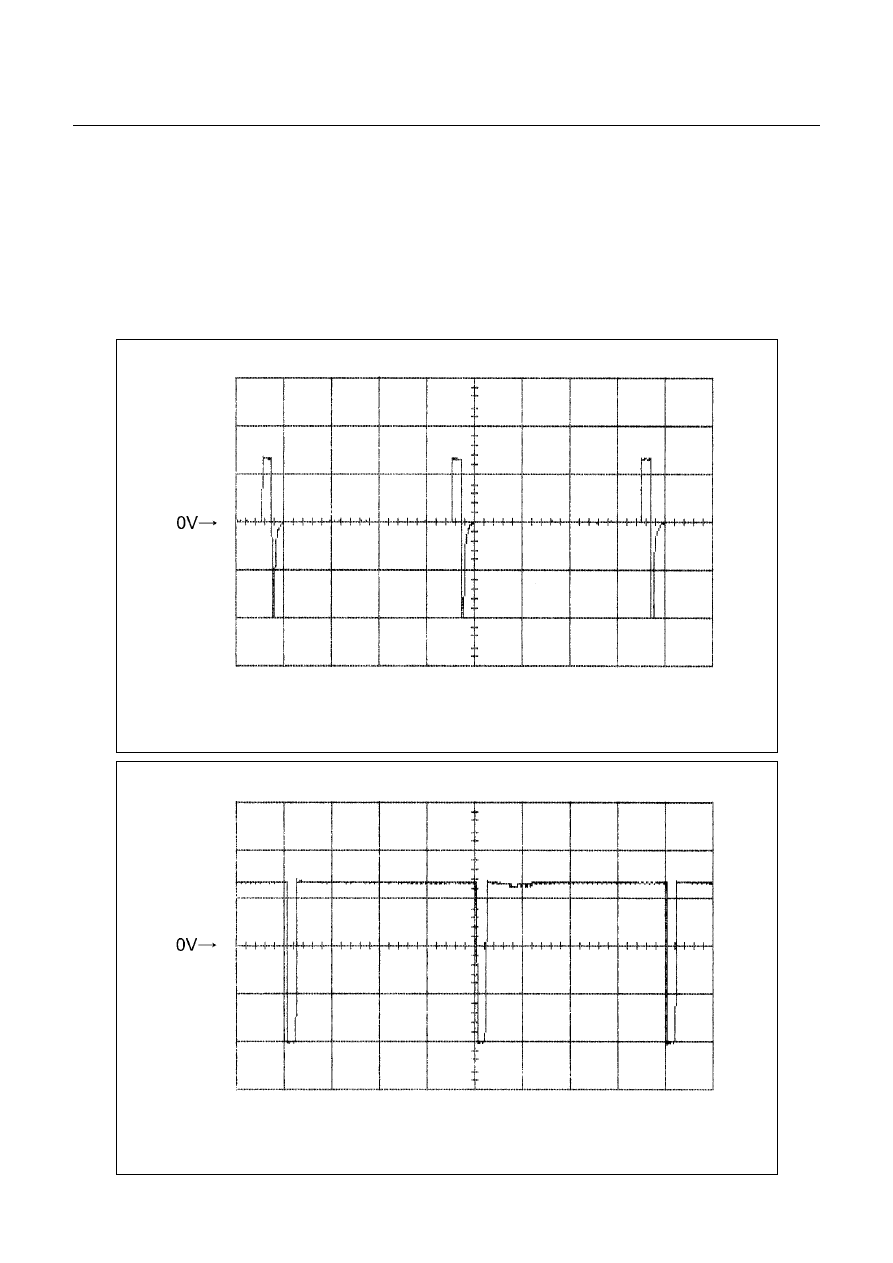
When the lock-up duty solenoid is operated, following signal is outputted.
Measurement terminal: B17 (C95) and B5 (C95)
-AC range by circuit tester: Approximately 7.2V
Lock-up Duty Solenoid Reference Wave Form
Measurement Terminal: B17 (+)
B5 (-)
Measurement Scale: 10V/div
5ms/div
Measurement Condition: Unlock-up condition
Lock-up Duty Solenoid Reference Wave Form
Measurement Terminal: B17 (+)
B5 (-)
Measurement Scale: 10V/div
5ms/div
Measurement Condition: Lock-up condition

DIAGNOSIS 7A2-65
DTC P1853 (Flash Code 26) Low & Reverse Brake Pressure Switch Failure
Control Valve
TCM
B1
B12
B20
RED/YEL
WHT/BLK
2-4 Brake Pressure SW
Terminal
Assembly
YEL
E54
(7)
(12)
(1)
H23
(12)
(10)
C95
(1)
(12)
(20)
RED/YEL
YEL
WHT/BLK
L&R Brake Pressure SW
High Clutch Pressure SW
H22
(8)
Pre-setting Condition:
•
No gear shifting.
•
No Check Trans indicator lamp.
•
No system voltage failure.
•
No inhibitor switch failure.
•
Low & reverse brake duty solenoid 0 or 100 %.
•
ATF temperature more than 60
°
C.
•
ATF input voltage more than 0.1V.
•
Engine speed more than 500 rpm.
7A2-66 DIAGNOSIS
Setting Condition:
•
During the running, the low & reverse brake pressure switch does not turn on though hydraulic pressure is
supposed to be generated in the low & reverse brake.
(All pre-setting conditions are met for 2.5 seconds, Low & reverse brake duty solenoid 0% and low & reverse
brake pressure switch off in R range)
Or
•
During the running, the low & reverse brake switch does not turn off though no hydraulic pressure is supposed to
be generated in the low & reverse brake.
(All pre-setting conditions are met for 2.5 seconds, 4th gear, all pressure switch on and gear ratio 0.652 - 0.735
in D range.)
Fail Safe:
•
No fail safe function
Possible Cause:
•
Low & reverse brake duty solenoid malfunction.
•
Low & reverse brake pressure switch wire open circuit or short circuit.
•
Open circuit, short circuit to battery or short circuit to ground between low & reverse brake pressure switch
terminal 12 and TCM terminal B12 (C95).
•
Low & reverse brake hydraulic circuit malfunction in the control valve.
•
Poor connection of each connector.
Reference:
When the low & reverse brake pressure switch is operated, following signal is outputted.
Measurement terminal: B12 (C95) and B22 (C95)
-At other than R rage or L range in 1st gear: More than 10V
-At R range or L range in 1 st gear: Less than 1V
Нет комментариевНе стесняйтесь поделиться с нами вашим ценным мнением.
Текст