Isuzu D-Max / Isuzu Rodeo (TFR/TFS). Manual — part 619

6F – 14 EXHAUST SYSTEM
IDENTIFICATION OF UNIT
The turbocharger nameplate gives the date of manufacture
and other important information required to identify the unit
when service inquiries are made.
The turbocharger nameplate has the following information
stamped on it.
Q
Turbo Specification Number, Production Year and
Month
R
Production Date, Daily Serial Number
S
ISUZU Parts Number
EXHAUST SYSTEM 6F – 15
INSPECTION AND REPAIR
Make the necessary adjustments, repairs, and part replacements if excessive wear or damage is discovered during
inspection.
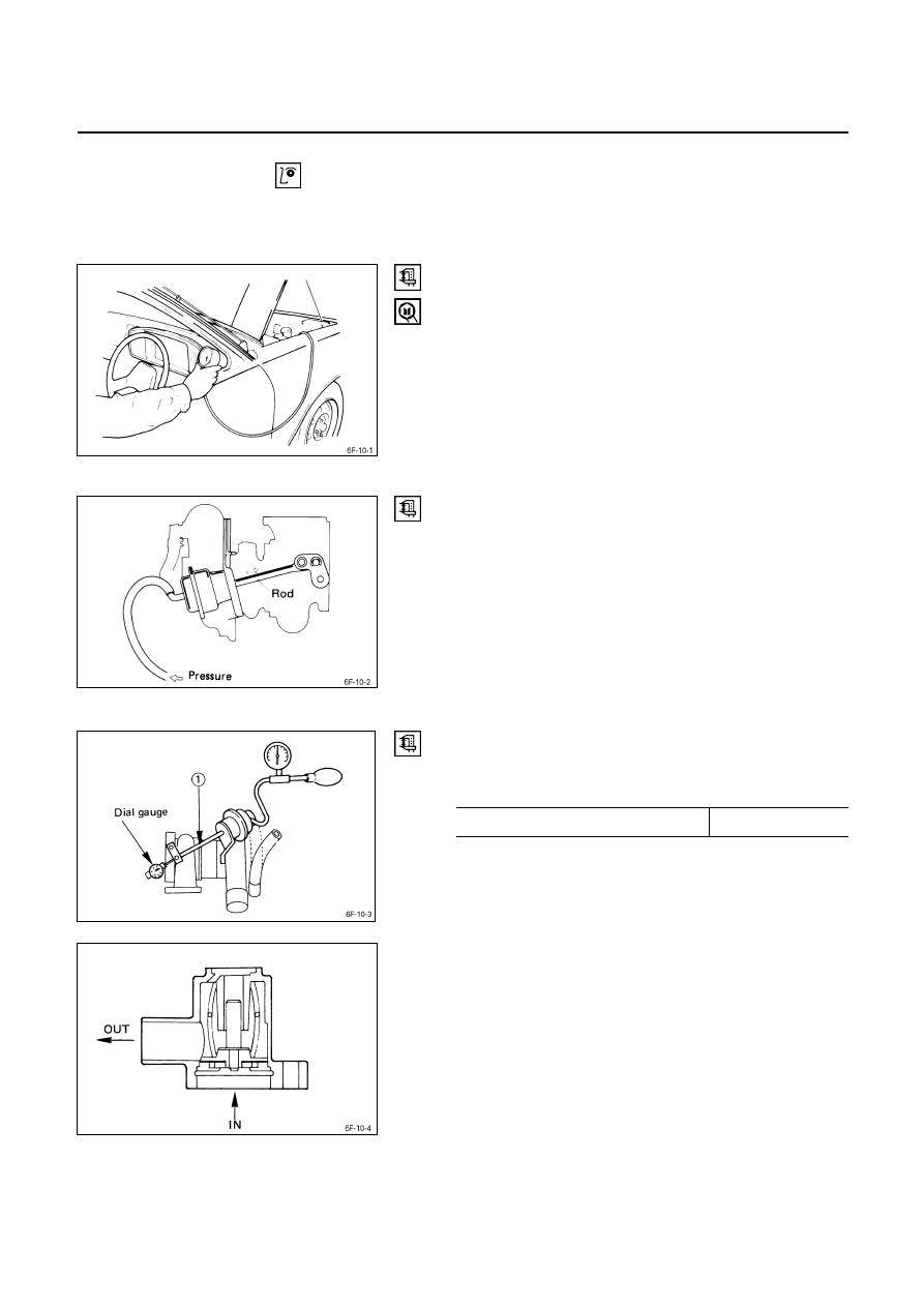
Turbocharger pressure check
(1) Remove the pressure switch connecting hose from
intake duct.
(2) Connect the pressure gauge.
(3) Start the engine and gradually increase the engine
speed (the vehicle must be stationary with no load
applied to the engine).
(4) Check to see that turbocharger pressure rises to
approximately 300 mmHg.
Pressure Gauge : 5-8840-0075-0
Waste gate operation check
(1) Remove the hose between the waste gate and the
intake pipe.
(2) Connect the pressure gauge.
(3) Check to see that the rod begins to move when a
pressure of approximately 665 mmHg is applied to the
waste gate.
Note:
Do not apply a pressure greater than 1 kg/cm
2
to the
wastegate during this check.
Unit Inspection (Remove Turbo. from engine)
Check to see the pressure required to move the control
rod
Q
2 mm is within the limits shown below.
Control Rod
Q
Operating Pressure Approx. 860 mmHg
Safety valve check
Operate the valve with your hand to check its operation.
Check the valve seal are for excessive wear or damage.
Contact the “ISUZU MOTORS LIMITED” Dealer service
department or “IHI SERVICE FACILITY” for major repairs
and maintenance.
Important wheel shaft end play and bearing clearance
standards and limits are included below for your reference.
6F – 16 EXHAUST SYSTEM
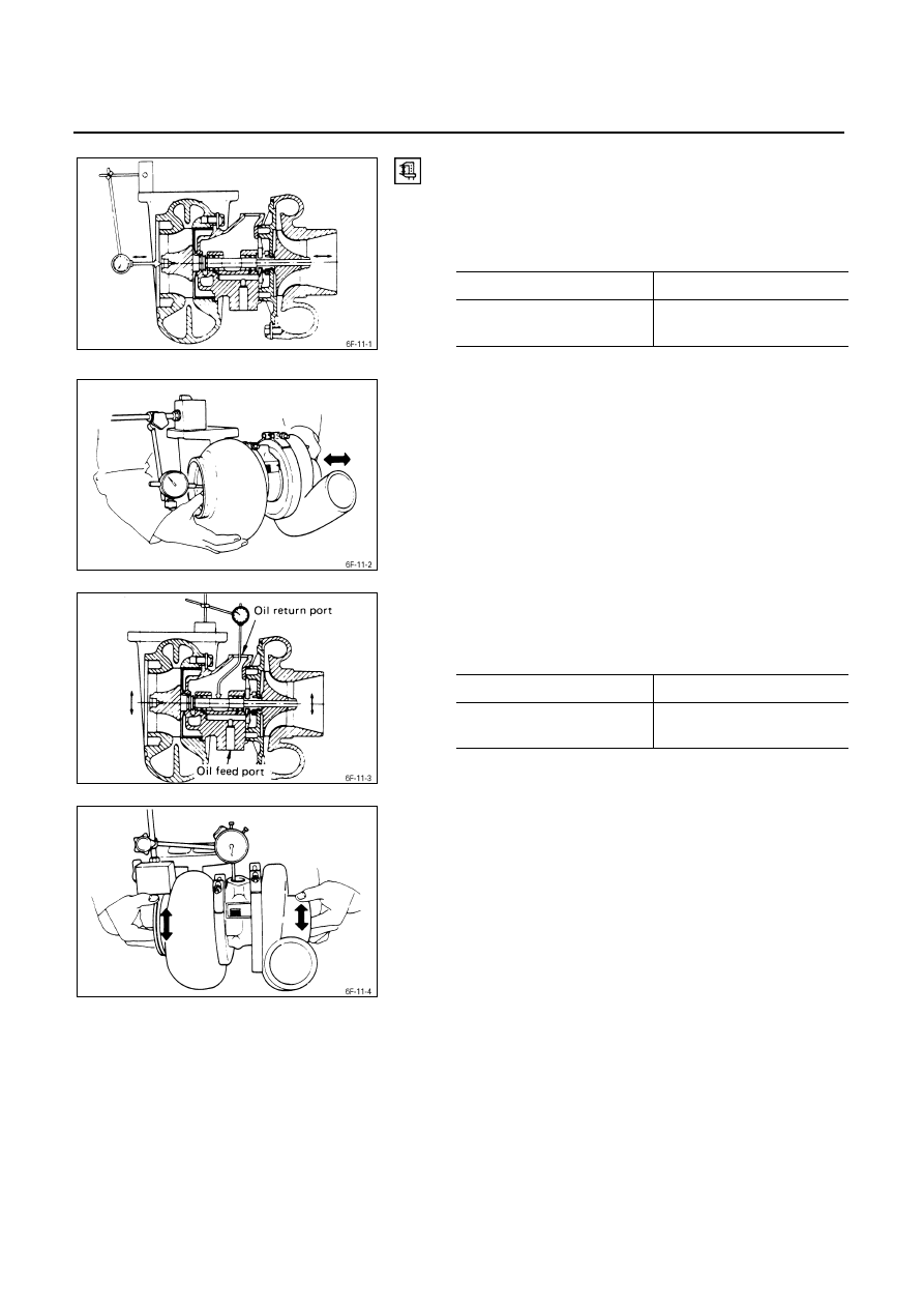
Wheel Shaft End Play
Use a dial indicator to measure the wheel shaft end play.
Apply a force of 1.2 kg (2.6 lb/11.8N) alternately to the
compressor wheel end and the turbine wheel end.
Wheel Shaft End Play
mm (in)
Standard Limit
0.03 - 0.06
(0.001 - 0.002)
0.09 (0.004)
Wheel Shaft and Bearing Clearance
Use a dial indicator to measure the wheel shaft and
bearing clearance.
Wheel Shaft and Bearing Clearance
mm (in)
Standard Limit
0.056 - 0.127
(0.0022 - 0.0050)
0.127 (0.0050)

EXHAUST SYSTEM 6F – 17
SPECIAL TOOLS
ILLUSTRATION
TOOL NUMBER
TOOL NAME
5-8840-0070-0 Pressure
Gauge
Нет комментариевНе стесняйтесь поделиться с нами вашим ценным мнением.
Текст