Isuzu D-Max / Isuzu Rodeo (TFR/TFS). Manual — part 221
ENGINE DRIVEABILITY AND EMISSIONS
6E–125
6
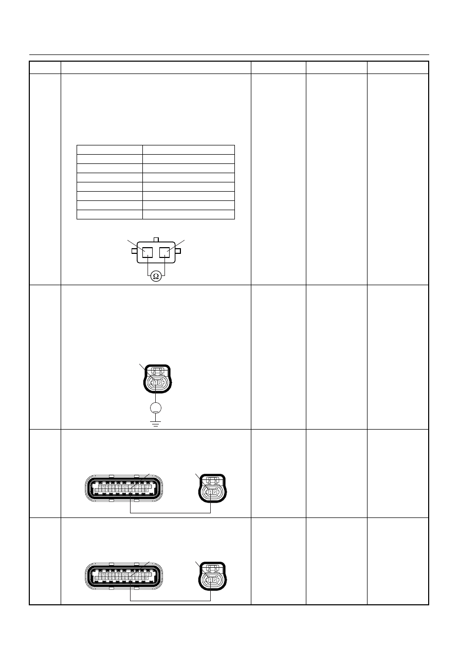
Using the DVM and check the IAT sensor.
1. Ignition “Off”, engine “Off”.
2. Disconnect IAT sensor connector.
3. Measure the resistance of IAT sensor.
Does the tester indicate standard resistance as shown
in the following table?
Standard
resistance
Go to Step 7
Go to Step 12
7
Using the DVM and check the IAT sensor signal
circuit.
1. Ignition “On”, engine “Off”.
2. Disconnect the IAT sensor connector.
3. Check the circuit for open circuit.
Was the DVM indicated specified value?
Approximately
5.0V
Go to Step 10
Less than 1V:
Go to Step 8
More than
specified value:
Go to Step 9
8
Repair the open circuit between the ECM and IAT
sensor.
Was the problem solved?
—
Verify repair
Go to Step 14
9
Repair the short to voltage circuit between the ECM
and IAT sensor.
Was the problem solved?
—
Verify repair
Go to Step 14
Step
Action
Value(s)
Yes
No
Temperature (°C)
Resistance (
Ω) (Approximately)
-20
32040
0
9788
20
3516
40
1439
60
656
80
327
100
175
IAT Sensor
1
1
2
2
V
C121
1
C56(J2)
C121
1
22
C56(J2)
C121
1
22
6E–126
ENGINE DRIVEABILITY AND EMISSIONS
10
Using the DVM and check the IAT sensor ground
circuit.
1. Ignition “On”, engine “Off”.
2. Disconnect the IAT sensor connector.
3. Check the circuit for short to power supply circuit.
Was the DVM indicated specified value?
Less than 1V
Go to Step 11
Repair faulty
harness and
verify repair
11
Using the DVM and check the IAT sensor ground
circuit.
Breaker box is available:
1. Ignition “Off”, engine “Off”.
2. Install the breaker box as type A. (ECM
disconnected) Ref. 6E-80.
3. Disconnect the IAT sensor connector.
4. Check the circuit for open circuit.
Was the problem found?
Breaker box is not available:
1. Ignition “Off”, engine “Off”.
2. Disconnect the IAT sensor connector.
3. Check the circuit for open circuit.
Was the problem found?
—
Repair faulty
harness and
verify repair
Go to Step 14
12
Substitute a known good IAT sensor assembly and
recheck.
Was the problem solved?
—
Go to Step 13
Go to Step 14
13
Replace the IAT sensor assembly.
Is the action complete?
—
Verify repair
—
14
Is the ECM programmed with the latest software
release?
If not, download the latest software to the ECM using
the “SPS (Service Programming System)”.
Was the problem solved?
—
Verify repair
Go to Step 15
Step
Action
Value(s)
Yes
No
V
C121
2
33
C121
2
C56(J2)
C121
2
1

ENGINE DRIVEABILITY AND EMISSIONS
6E–127
15
Replace the ECM.
Is the action complete?
IMPORTANT: The replacement ECM must be
programmed. Refer to section of the Service
Programming System (SPS) in this manual.
Following ECM programming, the immobiliser system
(if equipped) must be linked to the ECM. Refer to
section 11 “Immobiliser System-ECM replacement” for
the ECM/Immobiliser linking procedure.
—
Verify repair
—
Step
Action
Value(s)
Yes
No
6E–128
ENGINE DRIVEABILITY AND EMISSIONS
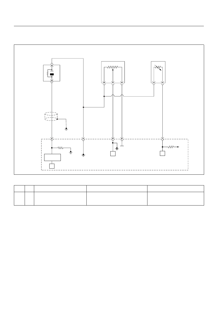
DIAGNOSTIC TROUBLE CODE (DTC) P0117 ENGINE COOLANT
TEMPERATURE SENSOR LOW INPUT
Condition for setting the DTC and action taken when the DTC sets
Circuit Description
The engine coolant temperature (ECT) sensor is a
thermistor mounted in the engine coolant stream. The
engine control module (ECM) applies a voltage (about 5
volts) through a pull-up resistor to the ECT signal circuit.
When the engine coolant is cold, the sensor (thermistor)
resistance is high, therefore the ECM will measure a
high signal voltage. As the engine coolant warms, the
sensor resistance becomes lower, and the ECT signal
voltage measured at the ECM drops. Diagnostic Trouble
code P0117 set when the ECM detects an excessively
low signal voltage on the engine coolant temperature
sensor signal circuit.
Diagnostic Aids
Check for the following conditions:
• Poor connection at ECM - Inspect harness
connectors for backed-out terminals, improper
mating, broken locks, improperly formed or damaged
terminals, and poor terminal-to-wire connection.
• Damaged harness - Inspect the wiring harness for
damage, short to ground, short to battery positive,
and open circuit. If the harness appears to be OK,
observe the ECT display on the Tech 2 while moving
connectors and wiring harnesses related to the ECT
sensor. A change in the ECT display will indicate the
location of the fault.
Code
Type
DTC Name
DTC Setting Condition
Fail-Safe (Back Up)
P0117
A
Engine Coolant Temperature Sensor
Low Input
1. Engine run time is longer than 120 sec-
onds.
2. ECT sensor output is more than 149°C.
The ECM uses default engine coolant
temperature value based on intake air
temperature and engine run time.
µP
0.5
GRY
J1-27
+5V
µP
µP
5Volts
Reference
Knock
Sensor
0.5
YEL
0.5
WHT/
BLU
J1-7
0.5
BLU/
PNK
J1-32
0.5
BLK/
YEL
J1-15
J1-3
Engine
Coolant
Temperature(ECT)
Sensor
Throttle
Position Sensor
Knock Filter
Module
Engine
Control
Module
(ECM)
Нет комментариевНе стесняйтесь поделиться с нами вашим ценным мнением.
Текст