Isuzu D-Max / Isuzu Rodeo (TFR/TFS). Manual — part 565
6A – 98 ENGINE MECHANICAL
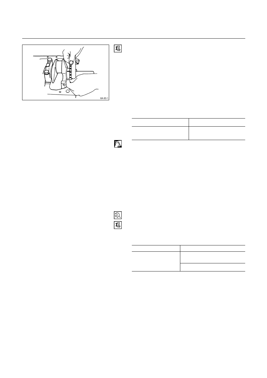
9. Compare the width of the Plastigage attached to either
the crankshaft or the bearing against the scale printed
on the Plastigage container.
If the measured value exceeds the limit, perform the
following additional steps.
1) Use a micrometer to measure the crankshaft
outside diameter.
2) Use an inside dial indicator to measure the
bearing inside diameter.
If the crankshaft journal and bearing clearance
exceeds the limit, the crankshaft and/or the
bearing must be replaced.
Crankshaft Journal and Bearing Clearance
mm (in)
Standard Limit
0.031 – 0.064
(0.0012 – 0.0025)
0.110 (0.0043)
Crankpin and Bearing Clearance
1. Clean the crankshaft, the connecting rod, the bearing
cap, and the bearings.
2. Install the bearing to the connecting rod and the
bearing cap.
Do not allow the crankshaft to move when installing
the bearing cap.
3. Prevent the connecting rod from moving.
4. Attach the Plastigage to the crankpin.
Apply engine oil to the Plastigage to keep it from
falling.
5. Install the bearing cap and tighten it to the specified
torque.
Do not allow the connecting rod to move when
installing and tightening the bearing cap.
Connecting Rod Bearing Cap Bolt
Torque kg·m
(lb.ft/N·m)
4JA1 / 4JA1T engine
8.5
± 0.5(61.4 ± 3.6 / 83.3 ± 4.9)
1st step ; 3.0
± 0.5(21.7 ± 3.6 /
29
± 5)
4JB1T / 4JG2T /
4JA1TC / 4JH1TC
engine
2nd step ; 45
° ~ 75°

ENGINE MECHANICAL 6A – 99
6. Remove the bearing cap.
7. Compare the width of the Plastigage attached to either
the crankshaft or the bearing against the scale printed
on the Plastigage container.
If the measured value exceeds the specified limit,
perform the following additional steps.
1) Use a micrometer to measure the crankpin
outside diameter.
2) Use an inside dial indicator to measure the
bearing inside diameter.
If the crank pin and bearing clearance exceeds the
specified limit, the crankshaft and/or the bearing
must be replaced.
Crankpin and Bearing Clearance
mm (in)
Standard Limit
0.029 – 0.066
(0.0011 – 0.0026)
0.100 (0.0039)
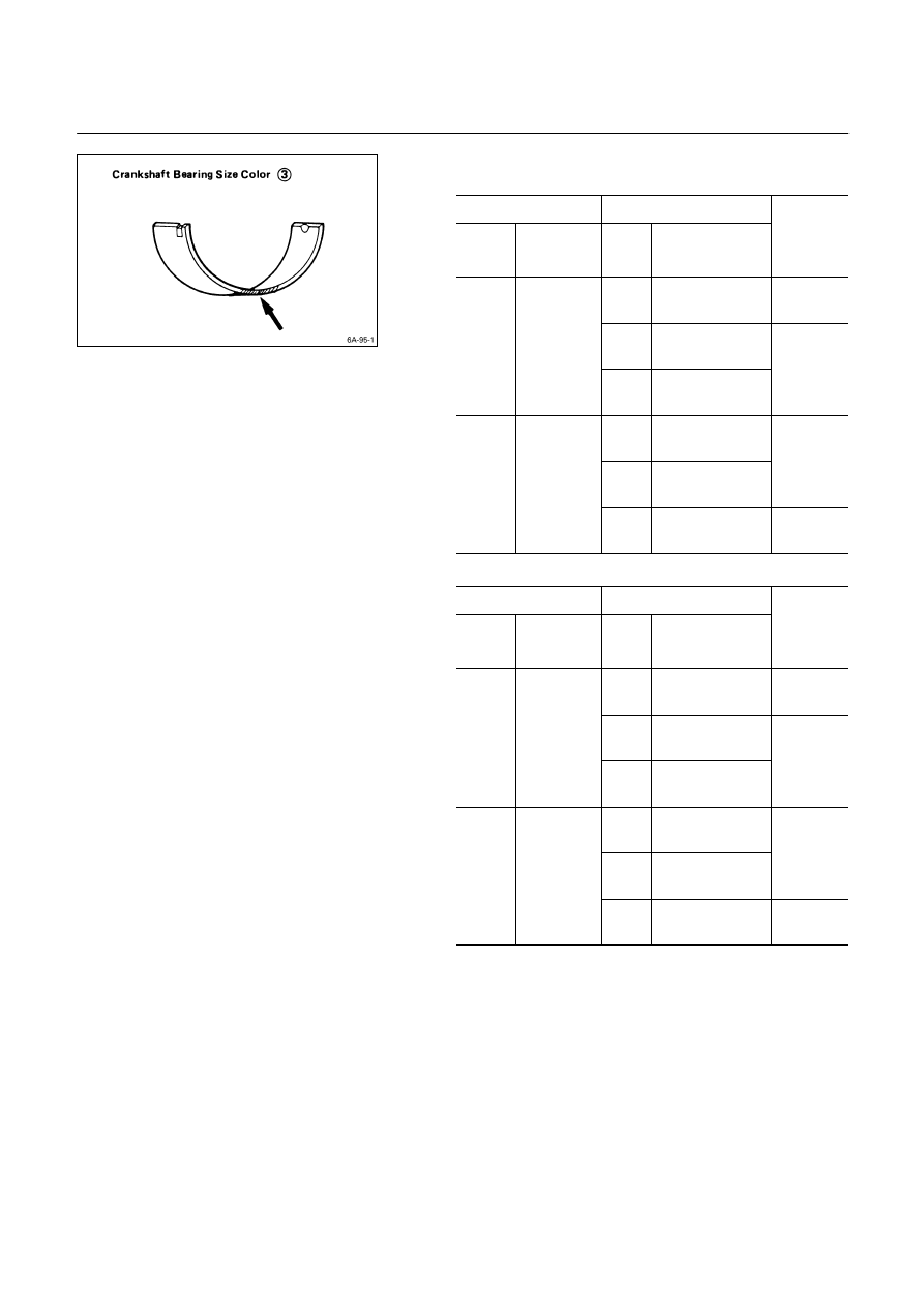
CRANKSHAFT BEARING SELECTION
Crankshaft bearing selection is based on the measured
diameters of the crankshaft journals and the bearing
inserts.
Match the crankshaft bearing housing grade marks and
the crankshaft journal grade marks in the table below to
determine the correct crankshaft bearing size.
Crankshaft Bearing Housing Grade Mark
Position
Crankshaft bearing housing grade marks 1 or 2 are
stamped on the rear right hand side of the cylinder body.
Example:
1
2
1
1
2
No. 1 Bearing
Housing
No. 2 Bearing
Housing
No. 3 Bearing
Housing
No. 4 Bearing
Housing
No. 5 Bearing
Housing
Crankshaft Journal Grade Mark Position
The crankshaft journal grade marks (1 or -) are stamped
on each crankshaft journal web.
The crankshaft journal and bearing clearance must be the
same for each position after installation of the crankshaft
and the crankshaft bearings.
Note:
The crankshaft journal mark No. 4 is stamped on
crankshaft No. 4 journal web front side or rear side.
6A – 100 ENGINE MECHANICAL
REFERENCE
4JA1, 4JA1T, 4JA1TC ENGINE mm
(in)
Crankshaft Bearing
Q
Crankshaft Journal
R
Grade
Mark
Diameter
Grade
Mark
Diameter
Crankshaft
Bearing
Size Color
Code
S
1 or
-
59.927 – 59.932
(2.3593 – 2.3595)
Black
2 or
- -
59.922 – 59.927
(2.3591 – 2.3593)
1
63.987 –
64.000
(2.5191 –
2.6196)
3 or
- - -
59.917 – 59.922
(2.3589 – 2.3591)
Blue
1 or
-
59.927 – 59.932
(2.3593 – 2.3595)
2 or
- -
59.922 – 59.927
(2.3591 – 2.3593)
Green
2
63.975 –
63.987
(2.5186 –
2.5191)
3 or
- - -
59.917 – 59.922
(2.3589 – 2.3591)
Black
4JB1T, 4JG2T, 4JH1TC ENGINE mm
(in)
Crankshaft Bearing
Q
Crankshaft Journal
R
Grade
Mark
Diameter
Grade
Mark
Diameter
Crankshaft
Bearing
Size Color
Code
S
1 or
-
69.927 – 69.932
(2.7530 – 2.7532)
Black
2 or
- -
69.922 – 69.927
(2.7528 – 2.7530)
1
73.987 –
74.000
(2.9129 –
2.9134)
3 or
- - -
69.917 – 69.922
(2.7556 – 2.7528)
Blue
1 or
-
69.927 – 69.932
(2.7530 – 2.7532)
2 or
- -
69.922 – 69.927
(2.7528 – 2.7530)
Green
2
73.975 –
73.987
(2.9124 –
2.9129)
3 or
- - -
69.917 – 69.922
(2.7556 – 2.7528)
Black

ENGINE MECHANICAL 6A – 101
CRANKSHAFT PILOT BEARING
Check the crankshaft pilot bearing for excessive wear and
damage and replace it if necessary.
Crankshaft Pilot Bearing Replacement
Crankshaft Pilot Bearing Removal
Use the pilot bearing remover to remove the crankshaft
pilot bearing.
Pilot Bearing Remover: 5-8840-2000-0
Sliding Hammer:
5-8840-0019-0 (J-23907)
Crankshaft Pilot Bearing Installation
1. Place the crankshaft pilot bearing right angle across
the crankshaft bearing installation hole.
2. Tap around the edges of the crankshaft pilot bearing
outer races with a brass hammer to drive the bearing
into the crankshaft bearing installation hole.
Pilot Bearing Installer: 5-8522-0024-0
Note:
Strike only the crankshaft pilot bearing outer race with
the hammer. Do not strike the bearing inner race.
Bearing damage and reduced bearing service life will
result.
Нет комментариевНе стесняйтесь поделиться с нами вашим ценным мнением.
Текст