Isuzu D-Max / Isuzu Rodeo (TFR/TFS). Manual — part 59

4JA1-TC/4JH1-TC ENGINE DRIVEABILITY AND EMISSIONS
6E–231
11
Is the ECM programmed with the latest software
release?
If not, download the latest software to the ECM using
the “SPS (Service Programming System)”.
Was the problem solved?
—
Verify repair
Go to Step 12
12
Replace the ECM.
Is the action complete?
IMPORTANT: The replacement ECM must be
programmed. Refer to section of the Service
Programming System (SPS) in this manual.
Following ECM programming, the immobiliser system
(if equipped) must be linked to the ECM. Refer to
section 11 “Immobiliser System-ECM replacement” for
the ECM/Immobiliser linking procedure.
—
Verify repair
—
Step
Action
Value(s)
Yes
No

6E–232
4JA1-TC/4JH1-TC ENGINE DRIVEABILITY AND EMISSIONS
DIAGNOSTIC TROUBLE CODE (DTC) P0704 (SYMPTOM CODE 6)
(FLASH CODE 57) CLUTCH SWITCH CIRCUIT MALFUNCTION
Condition for setting the DTC and action taken when the DTC sets
Circuit Description
The ECM monitors the clutch switch signal on the feed
terminal to the ECM. If clutch switch circuit with
malfunction, DTC P0704 (Symptom Code 6) will be
stored.
Diagnostic Aids
An intermittent may be caused by the following:
• Poor connections.
• Misrouted harness.
• Rubbed through wire insulation.
• Broken wire inside the insulation.
Check for the following conditions:
• Poor connection at ECM-Inspect harness connectors
for backed out terminals, improper mating, broken
locks, improperly formed or damaged terminals, and
poor terminal to wire connection.
• Damaged harness-Inspect the wiring harness for
damage. If the harness appears to be OK, observe
the “Clutch Switch” display on the Tech2 while moving
connectors and wiring harness related to the sensor.
Flash
Code
Code
Symptom
Code
MIL
DTC Name
DTC Setting Condition
Fail-Safe (Back Up)
57
P0704
6
ON
Clutch Switch Circuit Malfunc-
tion
Clutch signal does not change
between vehicle speed
1.5km/h and 80km/h since
ignition switch was tuned on.
No fail-safe function.
Battery
Voltage
Battery
Voltage
ECM
Main Relay
Stop
Light
10A
Injection
Pump
Stop
Lamp
IC
IC
CPU
0.5
BLU/
BLK
58
2.0
BLU/
RED
0.5
BLU/
RED
3
0.5
WHT/
BLK
65
0.85
RED
0.85
RED
0.85
GRN
30
0.5
BLU/
RED
63
0.5
YEL
31
0.5
RED/
BLK
0.5
BLU/
RED
0.5
BLU/
RED
0.85
WHT
0.5
WHT/
RED
0.5
RED/
GRN
Clutch
SW
Resister
Neutral
SW
87
0.5
BLU/
YEL
39
Brake
SW
M/T
A/T
Inhibitor
SW
Ignition
SW
Back,
Turn
15A
Engine
15A
µP
N
P
Engine
Control
Module
(ECM)
Batt
Batt
4JA1-TC/4JH1-TC ENGINE DRIVEABILITY AND EMISSIONS
6E–233
Diagnostic Trouble Code (DTC) P0704 (Symptom Code 6) (Flash Code 57)
Clutch Switch Circuit Malfunction
Step
Action
Value(s)
Yes
No
1
Was the “On-Board Diagnostic (OBD) System Check”
performed?
—
Go to Step 2
Go to On Board
Diagnostic
(OBD) System
Check
2
1. Connect the Tech 2.
2. Review and record the failure information.
3. Select “F0: Read DTC Infor As Stored By ECU” in
“F0: Diagnostic Trouble Codes”.
Is the DTC P0704 (Symptom Code 6) stored as
“Present Failure”?
—
Go to Step 3
Refer to
Diagnostic Aids
and Go to Step
3
3
1. Using the Tech 2, ignition “On” and engine “Off”.
2. Select “F1: Clear DTC Information” in “F0:
Diagnostic Trouble Codes” with the Tech 2 and
clear the DTC information.
3. Operate the vehicle and monitor the “F0: Read
DTC Infor As Stored By ECU” in the “F0:
Diagnostic Trouble Codes”.
Was the DTC P0704 (Symptom Code 6) stored in this
ignition cycle?
—
Go to Step 4
Refer to
Diagnostic Aids
and Go to Step
4
4
Check for poor/faulty connection at the clutch switch
or ECM connector. If a poor/faulty connection is found,
repair as necessary.
Was the problem found?
—
Verify repair
Go to Step 5
5
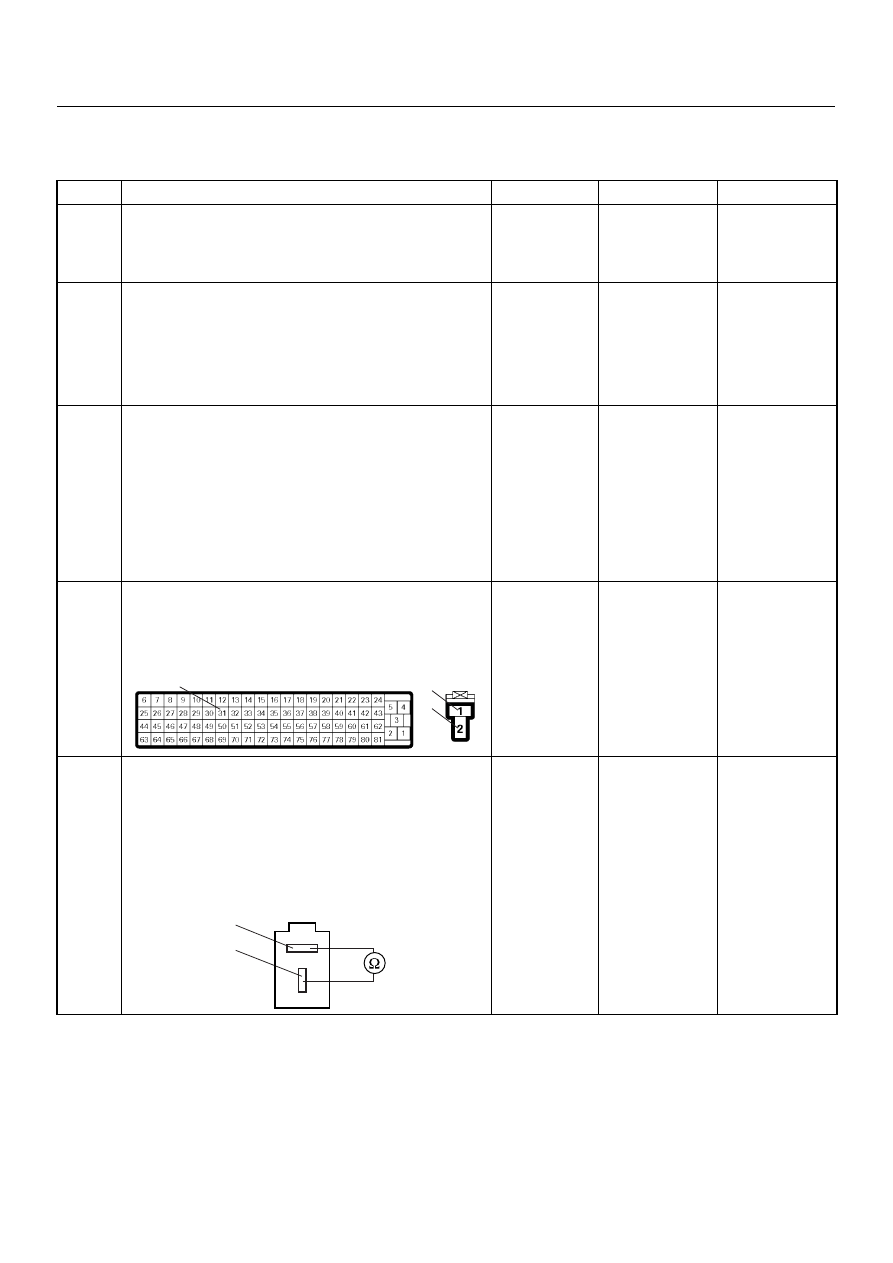
Using the DVM and check the clutch switch.
1. Ignition “Off”, engine “Off”.
2. Remove the clutch switch connector at the clutch
pedal.
3. Check the clutch switch.
Was the DVM indicated specified value?
Pedal is not
stepped on:
Continuity
Pedal stepped
on: No
continuity Go
to
Step 6
Replace pedal
switch and
verify repair
31
1
2
C-56
C-53
Clutch Switch
1
2
6E–234
4JA1-TC/4JH1-TC ENGINE DRIVEABILITY AND EMISSIONS
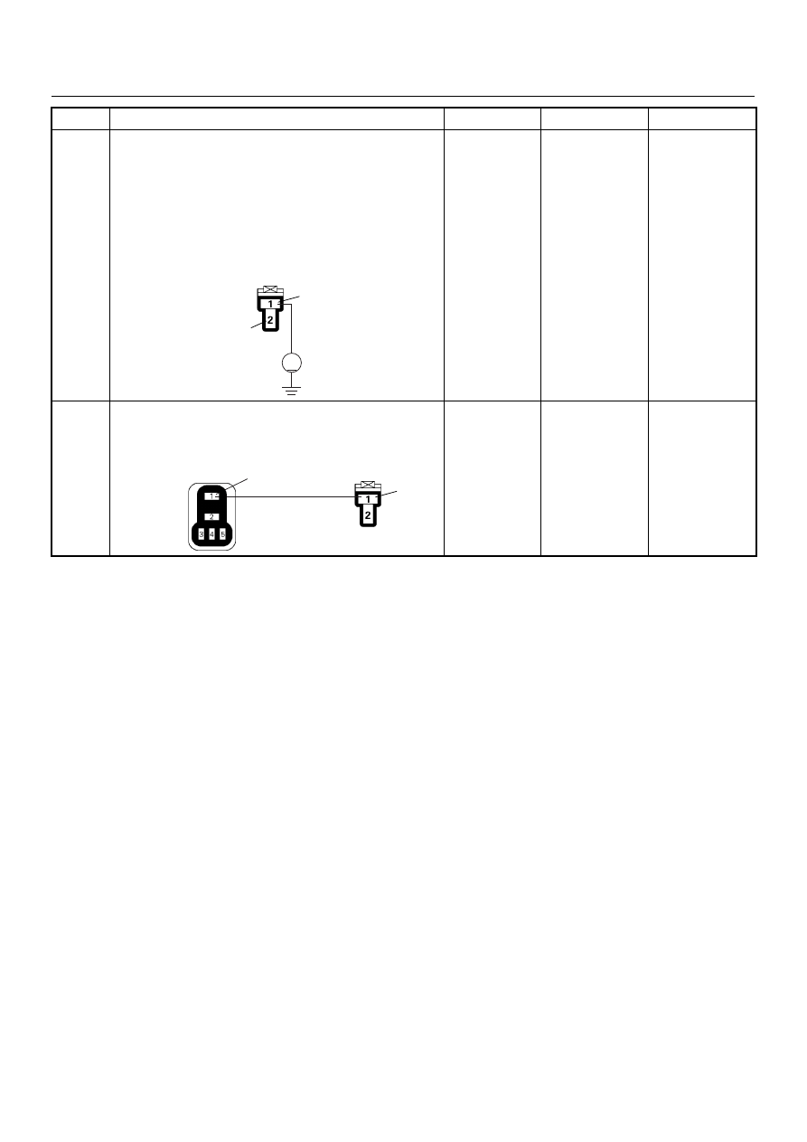
6
Using the DVM and check the clutch switch power
supply circuit.
1. Ignition “On”, engine “Off”.
2. Remove the clutch switch connector from the
clutch switch.
3. Check the circuit for open circuit.
Was the DVM indicated specified value?
Battery
voltage
Go to Step 8
Go to Step 7
7
Repair the open circuit between the “ECM Main
Relay” and clutch switch.
Is the action complete?
—
Verify repair
—
Step
Action
Value(s)
Yes
No
V
1
2
C-53
1
1
X-4
C-53
Нет комментариевНе стесняйтесь поделиться с нами вашим ценным мнением.
Текст