Isuzu D-Max / Isuzu Rodeo (TFR/TFS). Manual — part 2039

3B-46 STEERING
Ball Joints (Center Track Rod Assembly
and Outer Track Rod Track Rod
Assembly)
Inspect the following.
If one or more of the abnormal conditions listed in parenthesis
is discovered during inspection, the entire track rod
assembly(s) must be replaced.
1. Ball joint boot (Tearing and grease leakage)
2. Ball joint (Rough movement)
The ball joint must move smoothly with no snagging.
3. Ball joint screws (Excessive damage)
4. Ball joint tapered surfaces (Excessive wear and damage)

STEERING 3B-47
REASSEMBLY
Reassembly Steps
1. Center track rod assembly
2. Pin assembly
V
3. End assembly (inner)
V
4. Nut
V
5. End assembly (outer)
6. Relay lever
V
7. Nut
8. Pitman arm
V
9. Nut

3B-48 STEERING
Important operations
3. End Asseembly (Inner)
Align the setting marks applied at the disassembly.
End Assembly Torque
N
⋅
m (kgf
⋅
m/Ib
⋅
ft)
117.7
±
19.6 (12.0
±
2.0/86.8
±
14.5)
After tightening, stake the two portions securely.
5. End Assembly (Outer)
Align the setting marks applied during disassembly.
7. Nut
Relay Lever Nut Torque
N
⋅
m (kgf
⋅
m/Ib
⋅
ft)
58.8
+29.4
−
9.8
(6.0
+3
−
1
/43.4
+21.7
−
7.2
)
9. Nut
Pitman Arm Nut Torque
N
⋅
m (kgf
⋅
m/lb
⋅
ft)
98.0
+29.4
−
9.8
(10
+3
−
1
/72.3
+21.7
−
7.2
)
Note :
When change the track rod, adjust the track rod length.
mm (in)
4
×
2 (except Sporty)
306.9
±
1.5 (12.08
±
0.059)
4
×
4 and 4
×
2 Sporty
262
±
1.5 (10.31
±
0.059)
ADJUSTMENT
Adjust the toe-in angle.

STEERING 3B-49
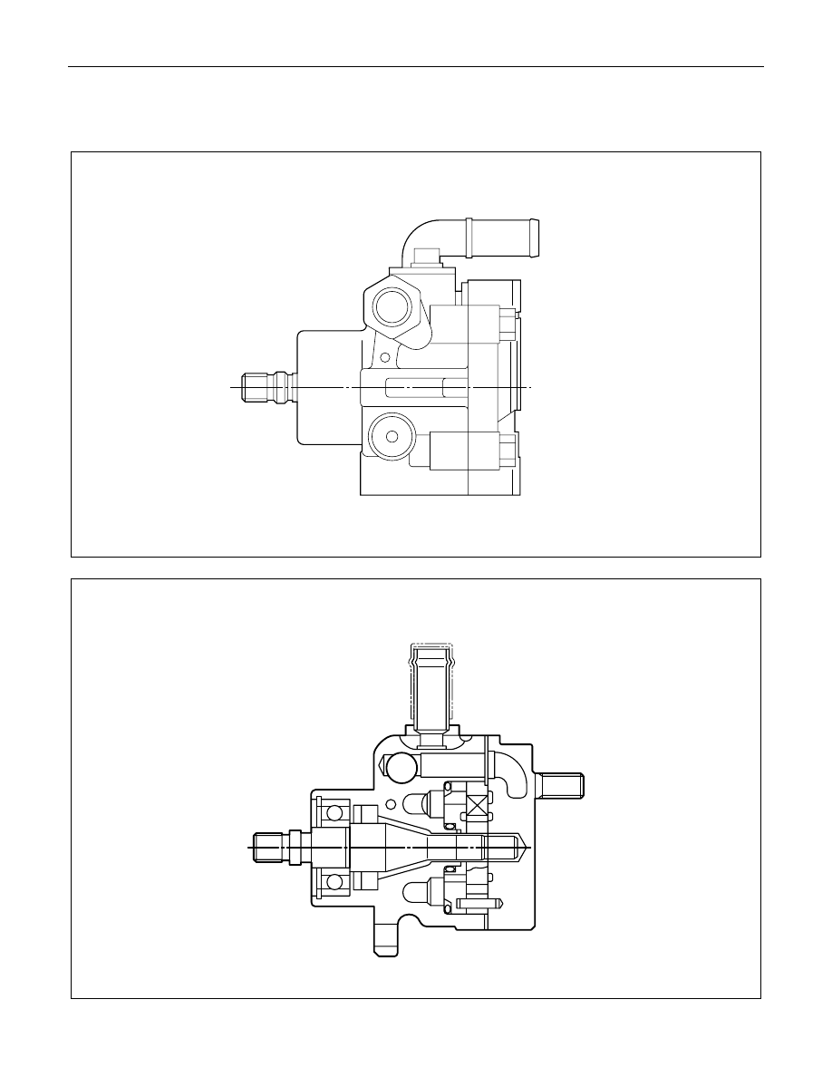
POWER STEERING OIL PUMP
GENERAL DESCRIPTION
C22, C20 Series Engine Model
4J Series Engine Model

Нет комментариевНе стесняйтесь поделиться с нами вашим ценным мнением.
Текст