Isuzu D-Max / Isuzu Rodeo (TFR/TFS). Manual — part 127
6E–112
4JH1 ENGINE DRIVEABILITY AND EMISSIONS
Diagnostic Trouble Code (DTC) P0110 (Symptom Code 2) (Flash Code 23)
Intake Air Temperature (IAT) Sensor Circuit Low Input
Step
Action
Value(s)
Yes
No
1
Was the “On-Board Diagnostic (OBD) System Check”
performed?
—
Go to Step 2
Go to On Board
Diagnostic
(OBD) System
Check
2
1. Connect the Tech 2.
2. Review and record the failure information.
3. Select “F0: Read DTC Infor As Stored By ECU” in
“F0: Diagnostic Trouble Codes”.
Is the DTC P0110 (Symptom Code 2) stored as
“Present Failure”?
—
Go to Step 3
Refer to
Diagnostic Aids
and Go to Step
3
3
1. Using the Tech 2, ignition “On” and engine “Off”.
2. Select “F1: Clear DTC Information” in “F0:
Diagnostic Trouble Codes” with the Tech 2 and
clear the DTC information.
3. Operate the vehicle and monitor the “F0: Read
DTC Infor As Stored By ECU” in the “F0:
Diagnostic Trouble Codes”.
Was the DTC P0110 (Symptom Code 2) stored in this
ignition cycle?
—
Go to Step 4
Refer to
Diagnostic Aids
and Go to Step
4
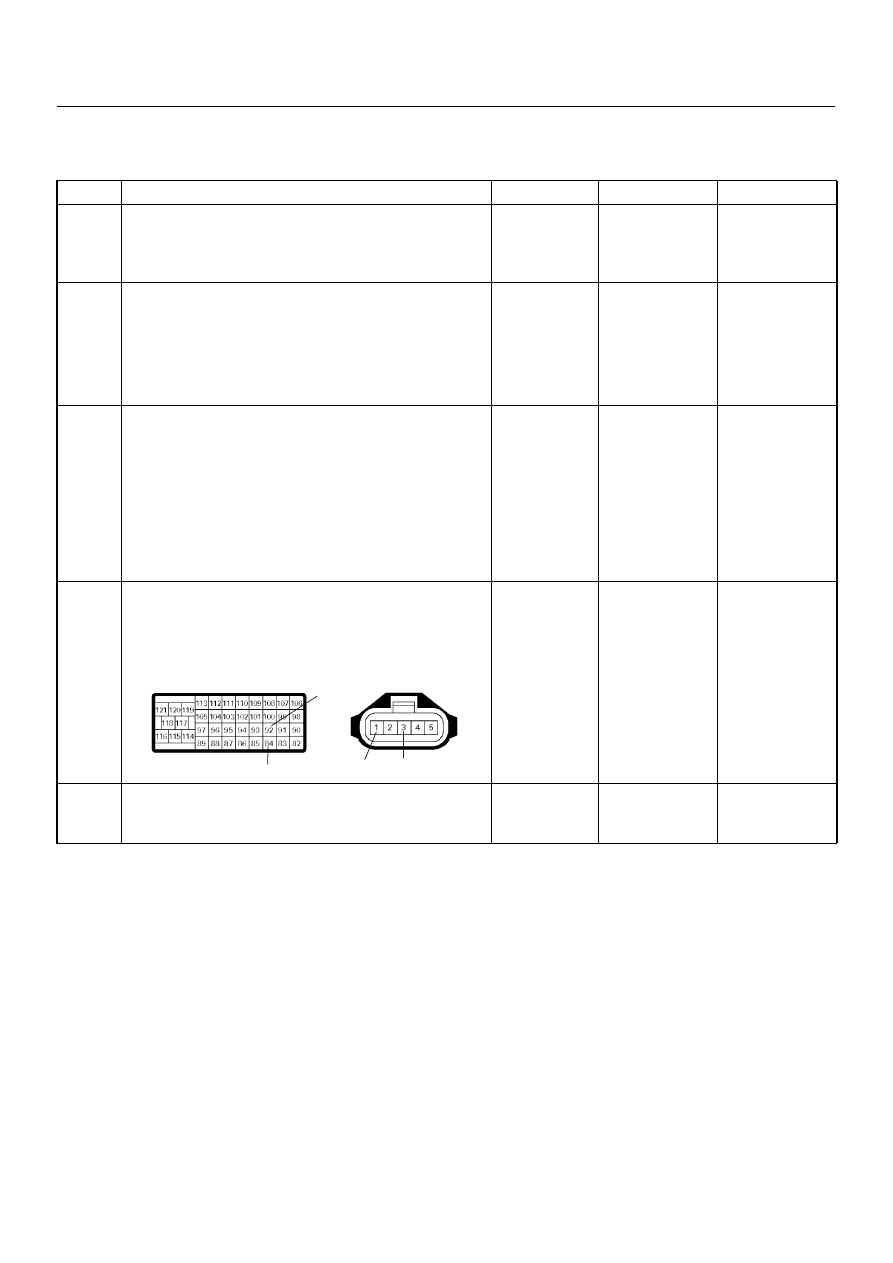
4
Check for poor/faulty connection at the IAT sensor or
ECM connector. If a poor/faulty connection is found,
repair as necessary.
Was the problem found?
—
Verify repair
Go to Step 5
5
Remove the MAF & IAT sensor assembly and visually
check.
Was the problem found?
—
Go to Step 8
Go to Step 6
92
84
1
3
C-116
C-57(B)
4JH1 ENGINE DRIVEABILITY AND EMISSIONS
6E–113
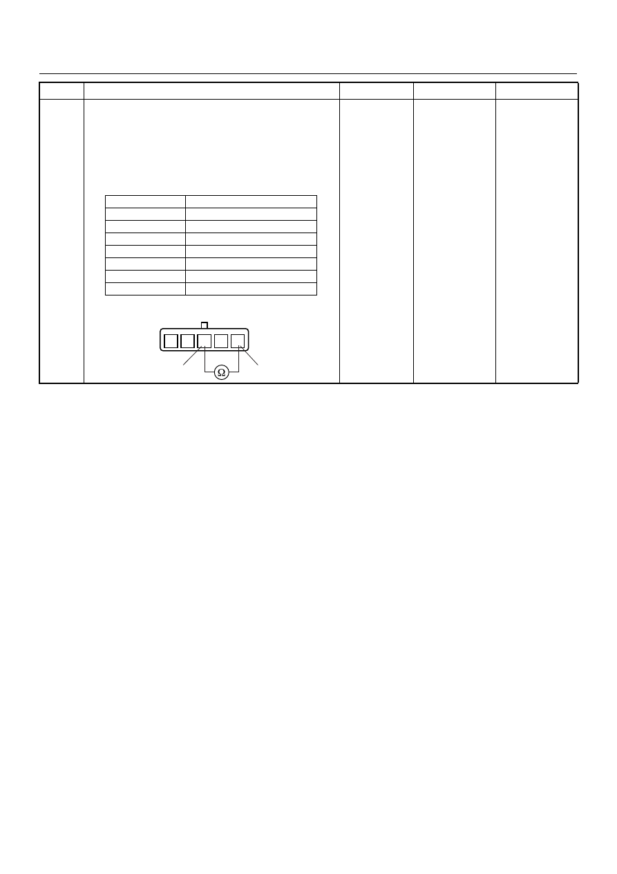
6
Using the DVM and check the IAT sensor.
1. Ignition “Off”, engine “Off”.
2. Disconnect MAF & IAT sensor connector.
3. Measure the resistance of IAT sensor.
Does the tester indicate standard resistance as shown
in the following table?
Standard
resistance
Go to Step 7
Go to Step 8
Step
Action
Value(s)
Yes
No
Temperature (°C)
Resistance (
Ω) (Approximately)
-20
14210
0
5402
20
2343
40
1131
60
596
80
338
100
203
1
2
3
5
4
1
3
IAT Sensor
6E–114
4JH1 ENGINE DRIVEABILITY AND EMISSIONS
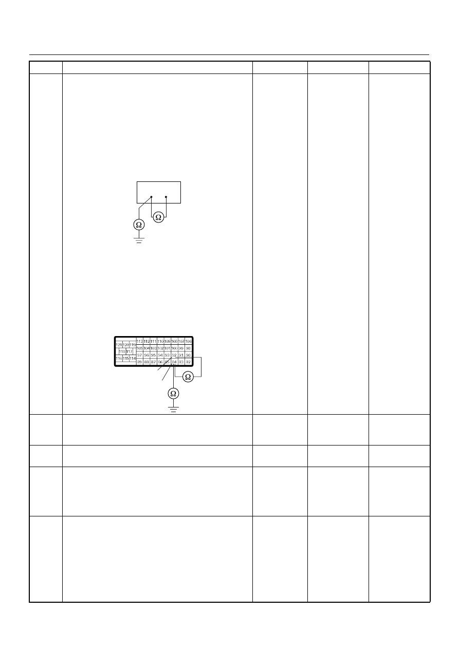
7
Using the DVM and check the IAT sensor signal
circuit.
Breaker box is available:
1. Ignition “Off”, engine “Off”.
2. Install the breaker box as type A. (ECM
disconnected) Ref. Page 6E-73
3. Disconnect the MAF & IAT sensor connector.
4. Check the circuit for short to sensor ground or
ground circuit.
Was the problem found?
Breaker box is not available:
1. Ignition “Off”, engine “Off”.
2. Disconnect the MAF & IAT sensor connector and
ECM connector.
3. Check the circuit for short to sensor ground or
ground circuit.
Was the problem found?
—
Repair faulty
harness and
verify repair
Go to Step 10
8
Substitute a known good MAF & IAT sensor assembly
and recheck.
Was the problem solved?
—
Go to Step 9
Go to Step 10
9
Replace the MAF & IAT sensor assembly.
Is the action complete?
—
Verify repair
—
10
Is the ECM programmed with the latest software
release?
If not, download the latest software to the ECM using
the “SPS (Service Programming System)”.
Was the problem solved?
—
Verify repair
Go to Step 11
11
Replace the ECM.
Is the action complete?
IMPORTANT: The replacement ECM must be
programmed. Refer to section of the Service
Programming System (SPS) in this manual.
Following ECM programming, the immobiliser system
(if equipped) must be linked to the ECM. Refer to
section 11 “Immobiliser System-ECM replacement” for
the ECM/Immobiliser linking procedure.
—
Verify repair
—
Step
Action
Value(s)
Yes
No
84
92
92
84
C-57(B)
4JH1 ENGINE DRIVEABILITY AND EMISSIONS
6E–115
DIAGNOSTIC TROUBLE CODE (DTC) P0115 (SYMPTOM CODE 1)
(FLASH CODE 14) ENGINE COOLANT TEMPERATURE SENSOR CIRCUIT HIGH
INPUT
DIAGNOSTIC TROUBLE CODE (DTC) P0115 (SYMPTOM CODE 2)
(FLASH CODE 14) ENGINE COOLANT TEMPERATURE SENSOR CIRCUIT LOW
INPUT
Condition for setting the DTC and action taken when the DTC sets
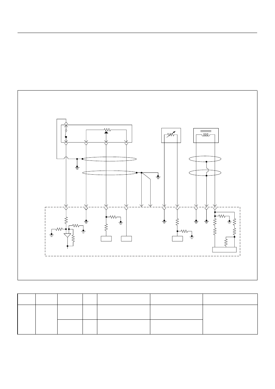
Circuit Description
The ECT sensor is a thermistor. A temperature changes
the resistance value. And it changes voltage. In other
words it measures a temperature value. It is installed on
the coolant stream. Low coolant temperature produces
a high resistance.
The ECM supplies 5 volts signal to the ECT sensor
through resisters in the ECM and measures the voltage.
The signal voltage will be high when the engine
Flash
Code
Code
Symptom
Code
MIL
DTC Name
DTC Setting Condition
Fail-Safe (Back Up)
14
P0115
1
ON
Engine Coolant Temperature
(ECT) Sensor Circuit High
Input
ECT sensor output voltage is
more than 4.7V.
1. ECM uses fuel temperature
as substitute.
2. ECM uses 60°C condition for
injection timing control.
3. ECM uses -15°C condition
for glow time control.
2
ON
Engine Coolant Temperature
(ECT) Sensor Circuit Low
Input
ECT sensor output voltage is
below 0.3V.
0.5
BLK
0.5
GRN/
BLK
69
0.5
RED
49
0.5
WHT
38
0.5
BLK
57
2.0
BLK
1
2.0
BLK
2
0.5
BLK/
PNK
93
0.5
GRY
ECT
Sensor
TPS &
Idle SW
89
0.5
WHT
98
101
0.5
RED
CKP
Sensor
90
IC
IC
IC
IC
Engine
Control
Module
(ECM)
Нет комментариевНе стесняйтесь поделиться с нами вашим ценным мнением.
Текст