Isuzu D-Max / Isuzu Rodeo (TFR/TFS). Manual — part 125

6E–104
4JH1 ENGINE DRIVEABILITY AND EMISSIONS
Diagnostic Trouble Code (DTC) P0100 (Symptom Code C) (Flash Code 65)
Mass Air Flow (MAF) Sensor Output Circuit High Input
Step
Action
Value(s)
Yes
No
1
Was the “On-Board Diagnostic (OBD) System Check”
performed?
—
Go to Step 2
Go to On Board
Diagnostic
(OBD) System
Check
2
1. Connect the Tech 2.
2. Review and record the failure information.
3. Select “F0: Read DTC Infor As Stored By ECU” in
“F0: Diagnostic Trouble Codes”.
Is the DTC P0100 (Symptom Code C) stored as
“Present Failure”?
—
Go to Step 3
Refer to
Diagnostic Aids
and Go to Step
3
3
1. Using the Tech 2, ignition “On” and engine “Off”.
2. Select “F1: Clear DTC Information” in “F0:
Diagnostic Trouble Codes” with the Tech 2 and
clear the DTC information.
3. Operate the vehicle and monitor the “F0: Read
DTC Infor As Stored By ECU” in the “F0:
Diagnostic Trouble Codes”.
Was the DTC P0100 (Symptom Code C) stored in this
ignition cycle?
—
Go to Step 4
Refer to
Diagnostic Aids
and Go to Step
4
4
Check for poor/faulty connection at the MAF sensor or
ECM connector. If a poor/faulty connection is found,
repair as necessary.
Was the problem found?
—
Verify repair
Go to Step 5
5
Visually check the MAF sensor.
Was the problem found?
—
Go to Step 11
Go to Step 6
92
88
83
2 3
4
5
C-116
C-57(B)
4JH1 ENGINE DRIVEABILITY AND EMISSIONS
6E–105
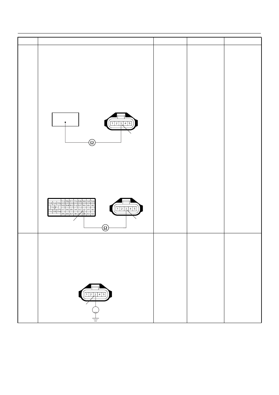
6
Using the DVM and check the MAF sensor ground
circuit.
Breaker box is available:
1. Ignition “Off”, engine “Off”.
2. Install the breaker box as type A. (ECM
disconnected) Ref. Page 6E-73
3. Disconnect the MAF sensor connector.
4. Check the circuit for open circuit.
Was the problem found?
Breaker box is not available:
1. Ignition “Off”, engine “Off”.
2. Disconnect the MAF sensor connector and ECM
connector.
3. Check the circuit for open circuit.
Was the problem found?
—
Repair faulty
harness and
verify repair
Go to Step 7
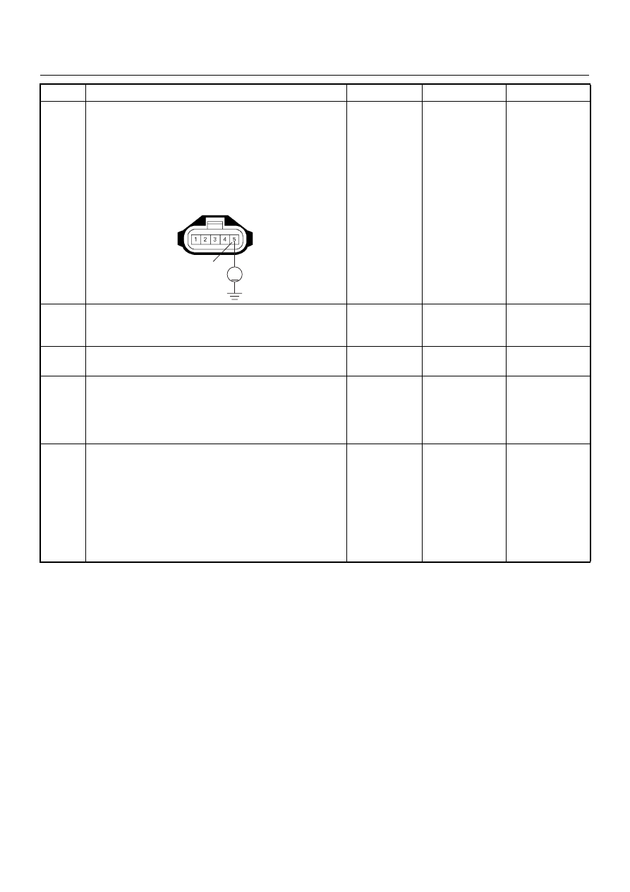
7
Using the DVM and check the MAF sensor ground
circuit.
1. Ignition “On”, engine “Off”.
2. Disconnect the MAF sensor connector .
3. Check the circuit for short to power supply circuit.
Was the DVM indicated specified value?
Less than 1V
Go to Step 8
Repair faulty
harness and
verify repair
Step
Action
Value(s)
Yes
No
92
3
C-116
3
92
C-116
C-57
3
V
C-116
6E–106
4JH1 ENGINE DRIVEABILITY AND EMISSIONS
8
Using the DVM and check the MAF sensor signal
circuit.
1. Ignition “On”, engine “Off”.
2. Disconnect the MAF sensor connector.
3. Check the circuit for short to power supply circuit.
Was the DVM indicated specified value?
Less than 1V
Go to Step 9
Repair faulty
harness and
verify repair
9
Substitute a known good MAF & IAT sensor assembly
and recheck.
Was the problem solved?
—
Go to Step 10
Go to Step 11
10
Replace the MAF & IAT sensor assembly.
Is the action complete?
—
Verify repair
—
11
Is the ECM programmed with the latest software
release?
If not, download the latest software to the ECM using
the “SPS (Service Programming System)”.
Was the problem solved?
—
Verify repair
Go to Step 12
12
Replace the ECM.
Is the action complete?
IMPORTANT: The replacement ECM must be
programmed. Refer to section of the Service
Programming System (SPS) in this manual.
Following ECM programming, the immobiliser system
(if equipped) must be linked to the ECM. Refer to
section 11 “Immobiliser System-ECM replacement” for
the ECM/Immobiliser linking procedure.
—
Verify repair
—
Step
Action
Value(s)
Yes
No
5
V
C-116

4JH1 ENGINE DRIVEABILITY AND EMISSIONS
6E–107
DIAGNOSTIC TROUBLE CODE (DTC) P0110 (SYMPTOM CODE 1)
(FLASH CODE 23) INTAKE AIR TEMPERATURE (IAT) SENSOR CIRCUIT HIGH
INPUT
DIAGNOSTIC TROUBLE CODE (DTC) P0110 (SYMPTOM CODE 2)
(FLASH CODE 23) INTAKE AIR TEMPERATURE (IAT) SENSOR CIRCUIT LOW
INPUT
Condition for setting the DTC and action taken when the DTC sets
Circuit Description
The IAT sensor is a thermistor. A temperature changes
the resistance value. And it changes voltage. In other
words it measures a temperature value. Low air
temperature produces a high resistance.
Flash
Code
Code
Symptom
Code
MIL
DTC Name
DTC Setting Condition
Fail-Safe (Back Up)
23
P0110
1
ON
Intake Air Temperature (IAT)
Sensor Circuit High Input
IAT sensor output voltage is
more than 4.7V.
ECM use 0°C conditions as
substitute.
2
ON
Intake Air Temperature (IAT)
Sensor Circuit Low Input
IAT sensor output voltage is
below 0.3V.
Batt
µP
0.5
BLK/
URG
0.5
BLU/
RED
0.5
BLU/
RED
97
0.5
WHT/
RED
83
0.5
GRN/
RED
88
0.5
BLK/
RED
92
0.5
BLK/
BLU
84
IAT
Sensor
MAF &
IAT
Sensor
ECM
10A
EGR-
EVRV
2
4
5
3
1
ECM
Main Relay
IC
IC
CPU
Engine
Control
Module
(ECM)
Нет комментариевНе стесняйтесь поделиться с нами вашим ценным мнением.
Текст