Isuzu D-Max / Isuzu Rodeo (TFR/TFS). Manual — part 181

6E–328
4JH1 ENGINE DRIVEABILITY AND EMISSIONS
34
Replace the injection pump assembly.
Is the action complete?
—
Verify repair
—
Step
Action
Value(s)
Yes
No

4JH1 ENGINE DRIVEABILITY AND EMISSIONS
6E–329
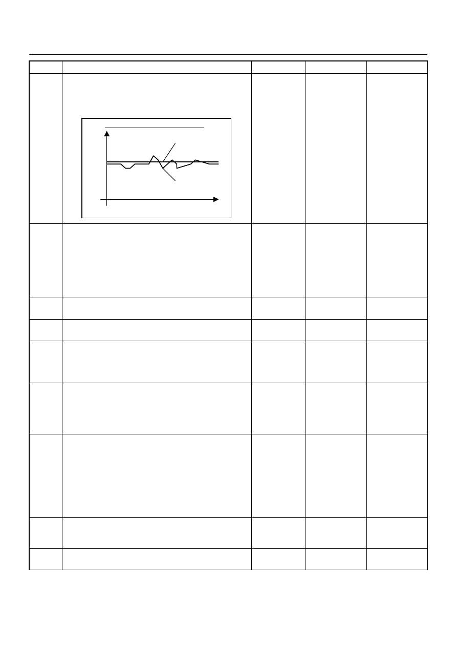
CUTS OUT, MISSES SYMPTOM
DEFINITIONS: Steady pulsation or jerking that follows
engine speed; usually more pronounced as engine load
increases.
time
rpm
Step
Action
Value(s)
Yes
No
1
Was the “On-Board Diagnostic (OBD) System Check”
performed?
—
Go to Step 2
Go to On Board
Diagnostic
(OBD) System
Check
2
1. Perform a bulletin search.
2. If a bulletin that addresses the symptom is found,
correct the condition as instructed in the bulletin.
Was a bulletin found that addresses the symptom?
—
Verify repair
Go to Step 3
3
Was a visually/physical check performed?
—
Go to Step 4
Go to Visual /
physical Check
4
Is the customer using the incorrect fuel type?
Diesel fuel
only
Replace with
diesel fuel
Go to Step 5
5
Visually/physically inspect for the following conditions.
• Restrict air intake system. Check for a restricted air
filter element, or foreign objects blocking the air
intake system
• Check for objects blocking or excessive deposits in
the throttle bore and on the throttle plate
• Check for a condition that causes a large vacuum
leak, such as an incorrectly installed or faulty
crankcase ventilation hose.
• Restrict air intake system at the turbocharger.
Check for objects blocking the turbocharger
compressor
wheel or turbine shaft sticking.
If a problem is found, repair as necessary.
Was a problem found?
—
Verify repair
Go to Step 6
6
Check the ECM & PSG grounds to verify that they are
clean and tight. Refer to the ECM wiring diagrams.
Was a problem found?
—
Verify repair
Go to Step 7
6E–330
4JH1 ENGINE DRIVEABILITY AND EMISSIONS
7
1. Using the Tech 2, perform test drive.
2. Monitor the “Vehicle Speed” in the data display.
Does the Tech 2 indicate correct “Vehicle Speed”
depending on driving speed?
—
Go to Step 11
Go to Step 8
8
Check the VSS harness for the following conditions.
• Check for poor connector connection.
• Check for misrouted harness.
• Check for any accessory parts which may cause
electric interference.
If a problem is found, repair as necessary.
Was a problem found?
—
Verify repair
Go to Step 9
9
Substitute a known good VSS and recheck.
Was the problem solved?
—
Go to Step 10
Go to Step 31
10
Replace the VSS assembly.
Is the action complete?
—
Verify repair
—
11
1. Using the Tech 2, ignition “On” and engine “Run”.
2. Monitor the “Mass Air Flow” in the data display.
Does the Tech 2 indicate correct “Mass Air Flow”
depending on accelerator pedal operation?
—
Go to Step 16
Go to Step 12
12
Remove the MAF & IAT sensor assembly and check
for the following conditions.
• Objects blocking at the MAF sensor element.
If a problem is found, repair as necessary.
Was the problem found?
—
Verify repair
Go to Step 13
13
Check the MAF sensor harness for the following
conditions.
• Check for poor connector connection.
• Check for misrouted harness.
• Check for any accessory parts which may cause
electric interference.
If a problem is found, repair as necessary.
Was a problem found?
—
Verify repair
Go to Step 14
14
Substitute a known good MAF & IAT sensor assembly
and recheck.
Was the problem solved?
—
Go to Step 15
Go to Step 31
15
Replace the MAF & IAT sensor assembly.
Is the action complete?
—
Verify repair
—
Step
Action
Value(s)
Yes
No
When constant vehicle speed
High
Correct Speed
Low
Time
Unstable Data

4JH1 ENGINE DRIVEABILITY AND EMISSIONS
6E–331
16
1. Using the Tech 2, ignition “On” and engine “Off”.
2. Monitor the “Pedal/Throttle Position” and “Idle
Switch” in the data display.
Does the Tech 2 indicate correct “Pedal/Throttle
Position” from 0% to 100% and correct “Idle Switch”
status depending on accelerator pedal operation?
—
Go to Step 21
Go to Step 17
17
1. Using the Tech 2, ignition “On” and engine “Off”.
2. Monitor the “Pedal/Throttle Position” and “Idle
Switch” in the data display.
3. Adjust the accelerator cable or TPS within 0% to
100%.
Was the problem solved?
—
Verify repair
Go to Step 18
18
Check the TPS harness for the following conditions.
• Check for poor connector connection.
• Check for misrouted harness.
• Check for any accessory parts which may cause
electric interference.
If a problem is found, repair as necessary.
Was a problem found?
—
Verify repair
Go to Step 19
19
Substitute a known good TPS and recheck.
Was the problem solved?
—
Go to Step 20
Go to Step 31
20
Replace the TPS.
Is the action complete?
—
Verify repair
—
21
Remove the CKP sensor from the flywheel housing
and check for the following conditions.
• Objects sticking the CKP sensor.
• Objects sticking the CKP sensor pulser.
If a problem is found, repair as necessary.
Was the problem found?
—
Verify repair
Go to Step 22
22
Check the CKP sensor harness for the following
conditions.
• Check for poor connector connection.
• Check for misrouted harness.
• Check for any accessory parts which may cause
electric interference.
If a problem is found, repair as necessary.
Was a problem found?
—
Verify repair
Go to Step 23
23
Substitute a known good CKP sensor and recheck.
Was the problem solved?
—
Go to Step 24
Go to Step 25
24
Replace the CKP sensor.
Is the action complete?
—
Verify repair
—
Step
Action
Value(s)
Yes
No
Нет комментариевНе стесняйтесь поделиться с нами вашим ценным мнением.
Текст