Isuzu D-Max / Isuzu Rodeo (TFR/TFS). Manual — part 182

6E–332
4JH1 ENGINE DRIVEABILITY AND EMISSIONS
25
1. Using the Tech 2 and ignition “On” and engine
“Run”.
2. Monitor the following parameters in the data
display.
• “Desired Injection Quantity” & “Injection Quantity”
• “Desired Injection Start” & “Actual Injection Start”
Are the large gap or unstable parameter displayed
between “Desired” and “Actual”?
—
Go to Step 29
Go to Step 26
26
Using the vacuum pump and check the EGR valve (if
equipped) operation for the following condition through
the small window.
• Restrict shaft movement. Check for objects sticking
the shaft, broken diaphragm or excessive carbon
deposit.
If a problem is found, repair as necessary.
Was a problem found?
—
Verify repair
Go to Step 27
27
Visually/physically inspect for the following conditions.
• Restrict fuel supply system. Check for a pinched
fuel hose/pipe.
• Check for a condition that causes fuel waxing or
icing, such as the customer is using an incorrect
fuel type in winter season or water mixed with the
fuel.
If a problem is found, repair as necessary.
Was a problem found?
—
Verify repair
Go to Step 28
28
Replace the fuel filter.
Was the problem solved?
—
Verify repair
Go to Step 29
Step
Action
Value(s)
Yes
No
When idling or part-throttle
High
Desired
Low
Time
Actual
Vacuum Pump
Small Window
4JH1 ENGINE DRIVEABILITY AND EMISSIONS
6E–333
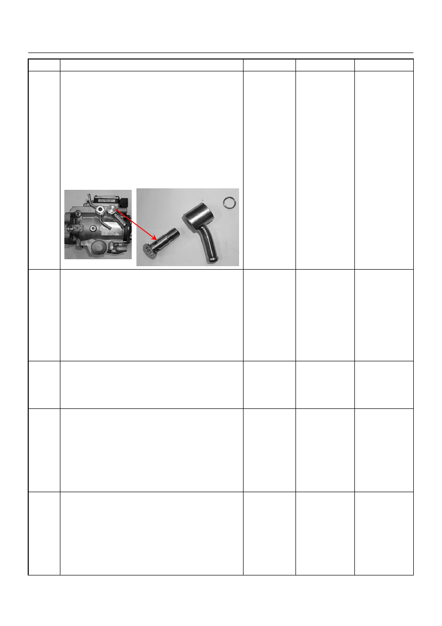
29
Remove the eye bolt with gauze filter from the
injection pump and check for the following conditions.
• Objects blocking at the gauze filter. Check for a
condition that causes contaminated fuel, such as
the customer is using an aftermarket fuel filter or
extended maintenance interval.
• Check for a condition that causes fuel waxing or
icing, such as the customer is using an incorrect
fuel type in winter season or water mixed with the
fuel.
If a problem is found, repair as necessary.
Was the problem found?
—
Replace the eye
bolt with gauze
filter and verify
repair
Go to Step 30
30
1. Review all diagnostic procedures within this table.
2. If all procedures have been completed and no
malfunctions have been found, review/inspect the
following:
• Visual/physical inspection
• Tech 2 data
• All electrical connections within a suspected circuit
and/or system
Was a problem found?
—
Verify repair
Go to Step 31
31
Is the ECM programmed with the latest software
release?
If not, download the latest software to the ECM using
the “SPS (Service Programming System)”.
Was the problem solved?
—
Verify repair
Go to Step 32
32
Substitute a known good ECM and recheck.
Was the problem solved?
IMPORTANT: The replacement ECM must be
programmed. Refer to section of the Service
Programming System (SPS) in this manual.
Following ECM programming, the immobiliser system
(if equipped) must be linked to the ECM. Refer to
section 11 “Immobiliser System-ECM replacement” for
the ECM/Immobiliser linking procedure.
—
Go to Step 33
Go to Step 34
33
Replace the ECM.
Is the action complete?
IMPORTANT: The replacement ECM must be
programmed. Refer to section of the Service
Programming System (SPS) in this manual.
Following ECM programming, the immobiliser system
(if equipped) must be linked to the ECM. Refer to
section 11 “Immobiliser System-ECM replacement” for
the ECM/Immobiliser linking procedure.
—
Verify repair
—
Step
Action
Value(s)
Yes
No

6E–334
4JH1 ENGINE DRIVEABILITY AND EMISSIONS
34
Replace the injection pump assembly.
Is the action complete?
—
Verify repair
—
Step
Action
Value(s)
Yes
No

4JH1 ENGINE DRIVEABILITY AND EMISSIONS
6E–335
LACK OF POWER, SLUGGISH OR SPONGY SYMPTOM
DEFINITIONS: Engine delivers less than expected power. Attempting part-throttle acceleration results in little or no
increase in vehicle speed.
Step
Action
Value(s)
Yes
No
1
Was the “On-Board Diagnostic (OBD) System Check”
performed?
—
Go to Step 2
Go to On Board
Diagnostic
(OBD) System
Check
2
1. Perform a bulletin search.
2. If a bulletin that addresses the symptom is found,
correct the condition as instructed in the bulletin.
Was a bulletin found that addresses the symptom?
—
Verify repair
Go to Step 3
3
Was a visually/physical check performed?
—
Go to Step 4
Go to Visual /
physical Check
4
Is the customer using the incorrect fuel type?
Diesel fuel
only
Replace with
diesel fuel
Go to Step 5
5
Visually/physically inspect for the following conditions.
• Restrict air intake system. Check for a restricted air
filter element, or foreign objects blocking the air
intake system
• Check for objects blocking or excessive deposits in
the throttle bore and on the throttle plate
• Check for a condition that causes a large vacuum
leak, such as an incorrectly installed or faulty
crankcase ventilation hose.
• Restrict air intake system at the turbocharger.
Check for objects blocking the turbocharger
compressor wheel or turbine shaft sticking.
If a problem is found, repair as necessary.
Was a problem found?
—
Verify repair
Go to Step 6
6
Check the ECM & PSG grounds to verify that they are
clean and tight. Refer to the ECM wiring diagrams.
Was a problem found?
—
Verify repair
Go to Step 7
7
1. Using the Tech 2, display the ECT sensor and IAT
sensor value.
2. Check the displayed value.
Does the Tech 2 indicate correct temperature
depending on engine condition?
If a problem is found, repair as necessary.
Was the problem found?
—
Verify repair
Go to Step 8
8
1. Using the Tech 2, display the FT sensor value.
2. Check the displayed value.
Does the Tech 2 indicate correct temperature
depending on engine condition?
If a problem is found, repair as necessary.
Was the problem found?
—
Go to Step 30
Go to Step 9
9
1. Using the Tech 2, ignition “On” and engine “Run”.
2. Monitor the “Mass Air Flow” in the data display.
Does the Tech 2 indicate correct “Mass Air Flow”
depending on accelerator pedal operation?
—
Go to Step 14
Go to Step 10
Нет комментариевНе стесняйтесь поделиться с нами вашим ценным мнением.
Текст