Isuzu D-Max / Isuzu Rodeo (TFR/TFS). Manual — part 1477
8-8 ELECTRICAL-BODY AND CHASSIS
SPLICING WIRE
Open the Harness
If the harness is taped, remove the tape.
To avoid wire insulation damage, use a sewing "seam ripper"
(available from sewing supply stores) to cut open the harness.
If the harness has a black plastic conduit, simply pull out the
desired wire.
Cut the wire
Begin by cutting as little wire off the harness as possible.
You may need the extra length of wire later if you decide to cut
more wire off to change the location of a splice.
You may have to adjust splice locations to make certain that
each splice is at least 1-1/2" (40 mm) away from other splices,
harness branches, or connectors.
Strip the insulation
When replacing a wire, use a wire of the same size as the
original wire.
Check the stripped wire for nicks or cut stands.
If the wire is damaged, repeat the procedure on a new section
of wire.
The two stripped wire ends should be equal in length.
Crimp the Wires
Select the proper clip to secure the splice.
To determine the proper clip size for the wire being spliced,
follow the directions included with your clips.
Select the correct anvil on the crimper.
(On most crimpers your choice is limited to either a small or
large anvil.)
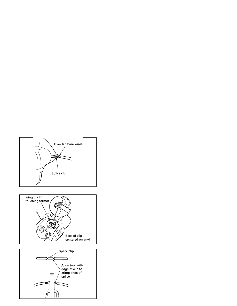
Overlap the two stripped wire ends and hold them between
your thumb and forefinger.
Then, enter the splice clip under the stripped wires and hold it
in place.
• Open the crimping tool to its full width and rest one handle
on a firm flat surface.
• Center the back of the splice clip on the proper anvil and
close the crimping tool to the point where the back of the
splice clip touches the wings of the clip.
• Make sure that the clip and wires are still in the correct
position. Then, apply pressure until the crimping tool closes.
Before crimping the ends of the clip, be sure that:
• The wires extend beyond the clip in each direction.
• No strands of wire are cut loose.
• No insulation is caught under the clip.
Crimp the splice again, once on each end.
Do not let the crimping tool extend beyond the edge of the clip
or you may damage or nick the wires.

ELECTRICAL-BODY AND CHASSIS 8-9
Solder
Apply 60/40 rosin core solder to the opening in the back of the
clip.
Follow the manufacturer's instructions for the solder equipment
you are using.
Tape the Splice
Center and roll the splicing tape.
The tape should cover the entire splice.
Roll on enough tape to duplicate the thickness of the insulation
on the existing wires.
Do not flag the tape.
Flagged tape may not provide enough insulation, and the
flagged ends will tangle with the other wires in the harness.
If the wire does not belong in a conduit or other harness
covering, tape the wire again.
Use a winding motion to cover the first piece of tape.

8-10 ELECTRICAL-BODY AND CHASSIS
SYMBOLS AND ABBREVIATIONS
SYMBOLS
Symbol
Meaning of Symbol
Symbol
Meaning of Symbol
Fuse
Bulb
Fusible link
Double filament bulb
Fusible link wire
Motor
Switch
Variable resistor Rheostat
Switch
Coil (inductor),solenoid,
magnetic valve
Switch (Normal close type)
Contact wiring
Relay
Battery
Diode
Connector
Electronic Parts
Light emitting diode
Resistor
Reed switch
Speaker
Condenser
Buzzer
Horn
Circuit breaker
Vacuum switching valve

ELECTRICAL-BODY AND CHASSIS 8-11
ABBREVIATIONS
Abbreviation
Meaning of abbreviation
Abbreviation
Meaning of abbreviation
A
Ampere(S)
LH
Left hand
ABS
Anti-lock brake system
LWB
Long wheel base
ASM
Assembly
MPI
Multiport fuel injection
AC
Alternating current
M/T
Manual transmission
A/C
Air conditioner
QOS
Quick On Start system
ACC
Accessories
RH
Right hand
CARB
Carburetor
RR
Rear
C/B
Circuit breaker
RWAL
Rear wheel anti-lock brake system
CSD
Cold start device
SRS
Supplemental restraint system
DIS
Direct ignition system
ST
Start
EBCM
Electronic brake control module
STD
Standard
ECGI
Electronic control gasoline injection
SW
Switch
ECM
Engine control module
SWB
Short wheel base
ECU
Electronic control unit
TCM
Transmission control module
EFE
Early fuel evaporation
V
Volt
4
×2
Two-wheel drive
VSV
Vacuum switching valve
4
×4
Four-wheel drive
W
Watt(S)
FL
Fusible link
WOT
Wide open throttle
FRT
Front
W/
With
H/L
Headlight
W/O
Without
IC
Integrated circuit
IG
Ignition
kW
kilowatt
Нет комментариевНе стесняйтесь поделиться с нами вашим ценным мнением.
Текст