Isuzu D-Max / Isuzu Rodeo (TFR/TFS). Manual — part 1476
8-4 ELECTRICAL-BODY AND CHASSIS
NOTES FOR WORKING ON ELECTRICAL ITEMS
BATTERY CABLE
Disconnecting the Battery Cable
1. All switches should be "OFF" position.
2. Disconnect the battery ground cable.
3. Disconnect the battery positive cable.
CAUTION:
It is important that the battery ground cable be
disconnected first.
Disconnecting the battery positive cable first can result in
a short circuit.
Connecting the Battery Cable
Follow the disconnecting procedure in the reverse order to
connect the battery cables.
CAUTION:
Clean the battery terminal and apply light coat of grease to
prevent terminal corrosion.
CONNECTOR HANDLING
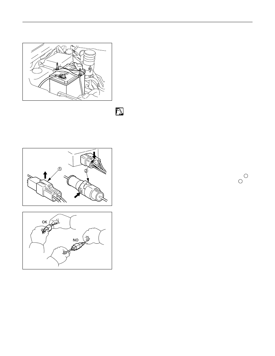
Disconnecting the Connectors
Some connectors have a tang lock to hold the connectors
together during vehicle operation.
Some tang locks are released by pulling them towards you
1
.
Other tang locks are released by pressing them forward
2
.
Determine which type of tang lock is on the connector being
handled.
Firmly grasp both sides (male and female) of the connector.
Release the tang lock and carefully pull the two halves of the
connector apart.
Never pull on the wires to separate the connectors.
This will result in wire breakage.
ELECTRICAL-BODY AND CHASSIS 8-5
Connecting the Connectors
Firmly grasp both sides (male and female) of the connector.
Be sure that the connector pins and pin holes match.
Be sure that both sides of the connector are aligned with each
other.
Firmly but carefully push the two sides of the connector
together until a distinct click is heard.
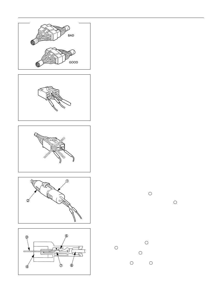
Connector Inspection
Use a circuit tester to check the connector for continuity.
Insert the test probes from the connector wire side.
CAUTION
Never insert the circuit tester test probes into the
connector open side to test the continuity.
Broken or open connector terminals will result.
Waterproof Connector Inspection
It is not possible to insert the test probes into the connector
wire side of a waterproof connector.
Use one side of a connector
1
with its wires cut to make the
test.
Connect the test connector to the connector
2
to be tested.
Connect the test probes to the cut wires to check the connector
continuity.
Connector Pin Removal
Connector Housing Tang Lock Type
1. Insert a slender shaft
3
into the connector housing open
end
4
.
2. Push the tang lock
5
up (in the direction of the arrow in the
illustration).
Pull the wire
6
with pin
7
free from the wire side of the
connector.
8-6 ELECTRICAL-BODY AND CHASSIS
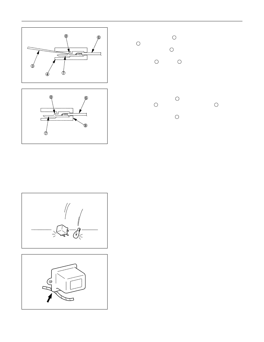
Pin Tang Lock Type
1. Insert a slender shaft
3
into the connector housing open
end
4
.
2. Push the tang lock
8
flat (toward the wire side of the
connector).
Pull the wire
6
with pin
7
free from the wire side of the
connector.
Connector Pin Insertion
1. Check that the tang lock
8
is fully up.
2. Insert the pin
7
from the connector wire side
9
.
Push the pin in until the tang lock closes firmly.
3. Gently pull on the wires
6
to make sure that connector pin
is firmly set in place.
Fuse Replacement
The replacement fuse must have the same amperage
specification as the original fuse.
Never replace a burn out fuse with a fuse of a different
amperage specification.
Doing so can result in an electrical fire or other serious circuit
damage.
Parts Handling
Be careful for parts handling and any part should not be
dropped or thrown, otherwise short circuit or disorder may
result.
Wiring Harness
1. When assembling the parts, be careful not to bite or wedge
the wiring harness.
2. All electrical connections must be kept be kept clean and
tight.
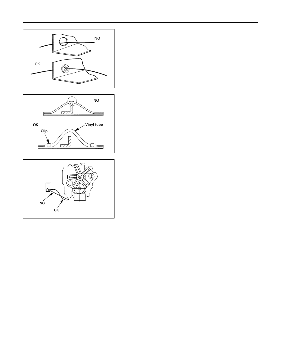
ELECTRICAL-BODY AND CHASSIS 8-7
3. Use a grommet or guard tube to protect the wiring harness
from contacting a sharp edge or surface.
4. Position the wiring harness with enough clearance from the
other parts and guard the wiring harness with a vinyl tube to
avoid direct contact.
5. The wiring harness between engine and chassis should be
long enough to prevent chafing or damage due to various
vibrations.
Нет комментариевНе стесняйтесь поделиться с нами вашим ценным мнением.
Текст