Isuzu D-Max / Isuzu Rodeo (TFR/TFS). Manual — part 552
6A – 46 ENGINE MECHANICAL
Transmission
1. Check that the lifting wires
Q
are securely attached.
2. Operate the hoist to slightly raise the engine.
Warning:
Take care not to lift the chassis from the chassis
stands.
If you do accidentally raise the chassis from the
chassis stands, make absolutely certain that the
chassis stands are correctly positioned before
lowering the chassis.
3. Place
the
jack
R
beneath the transmission case.
4. Operate the jack to slightly raise the transmission.
5. Remove the transmission member lower mounting
bolts
S
fixing the transmission member to the chassis
frame rail.
6. Loosen the engine mounting nuts
T
at the rubber
mountings.
7. Use the jack to slightly lower the transmission.
8. Remove the remaining transmission coupling bolts.
9. Separate the transmission from the engine.
Take care not to damage the transmission, the
engine, and their related parts.
10. Use the jack to lower the transmission together with
the mounting member to the floor.

ENGINE MECHANICAL 6A – 47
11. Remove the engine mounting bolts
U
from the
chassis frame.
12. Use the hoist to lift the engine from the engine
compartment.
Important Operations – Installation
Follow the removal procedure in the reverse order to
perform the installation procedure. Pay careful attention to
the important points during the installation procedure.
Engine
1. Attach a lifting wire to the engine lifting hanger.
2. Operate the hoist to position the engine above the
engine compertment.
Hold the front of the engine slightly higher than the
rear.
3. Slowly lower the engine into the engine compartment.
Be careful not to damage the brake pipes, the fuel
pipes, and other exposed parts.
4. Support the oil pan with a jack.
5. Temporarily tighten the engine front mounting rubber
nuts.
6A – 48 ENGINE MECHANICAL
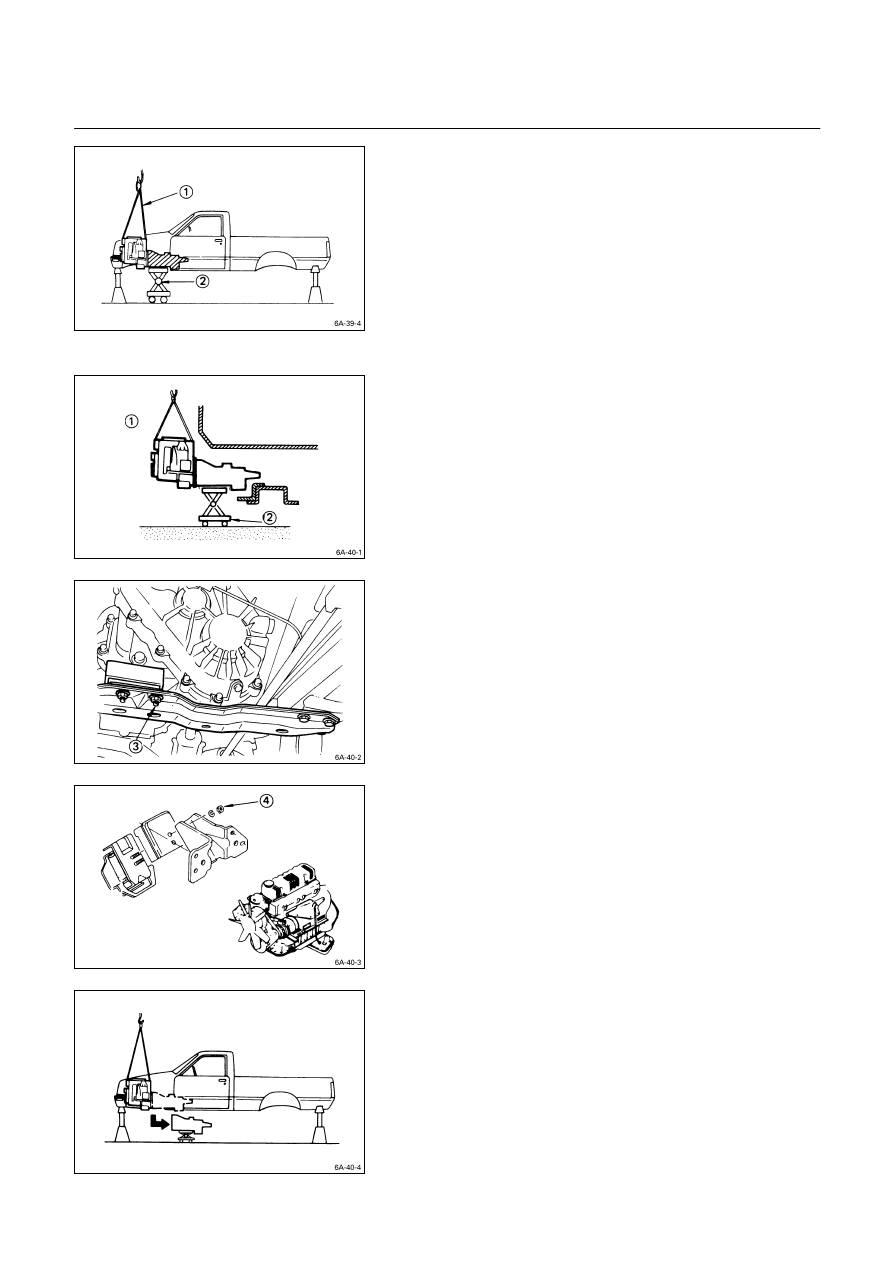
Transmission
1. Apply a thin coat of molybdenum disulfide grease to
the top gear shaft spline.
2. Place the transmission with the mounting rubbers on a
transmission jack.
3. Carefully move the transmission jack and
transmission into position behind the cab.
4. Slowly raise the transmission jack until the front of the
transmission is aligned with the engine flywheel.
The slope of the engine and the transmission must be
the same.
5. Align the top gear shaft spline with the clutch driven
plate internal spline.
6. Install the transmission to the engine.
Tighten the transmission coupling nuts and bolts to
the specified torque.
Transmission Coupling Nut and Bolt
Torque kg·m
(lb.ft/N·m)
3.8
± 0.8 (27.5 ± 5.8/37.2 ± 7.8)
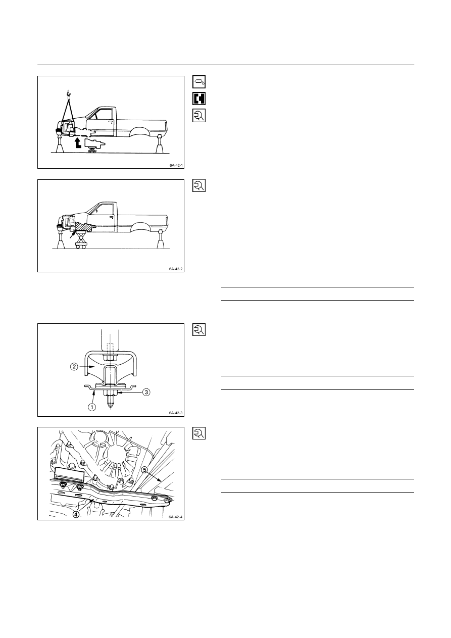
7. Install the mounting member
Q
to the mounting
rubber
R
.
8. Tighten the mounting member nuts
S
to the specified
torque.
Mounting Rubber Nut Torque
kg·m (lb.ft/N·m)
4.2
± 0.5 (30.4 ± 3.6/41.2 ± 4.9)
9. Install the mounting member
T
to the sidemembers
U
.
10. Tighten the mounting member bolts to the specified
torque.
Mounting Member Bolt Torque
kg·m (lb.ft/N·m)
7.8
± 1.6 (56.1 ± 11.2/76.0 ± 15.2)
ENGINE MECHANICAL 6A – 49
11. Tighten the engine mounting rubber nuts to the
specified torque.
Engine Mounting Rubber Nut Torque
kg·m (lb.ft/N·m)
4.2
± 0.5 (30.4 ± 3.6/41.2 ± 4.9)
Exhaust Pipe
Connect the exhaust pipe to the exhaust manifold.
Torque kg·m
(lb.ft/N·m)
6.8
± 0.5 (49 ± 3.6/67 ± 5)
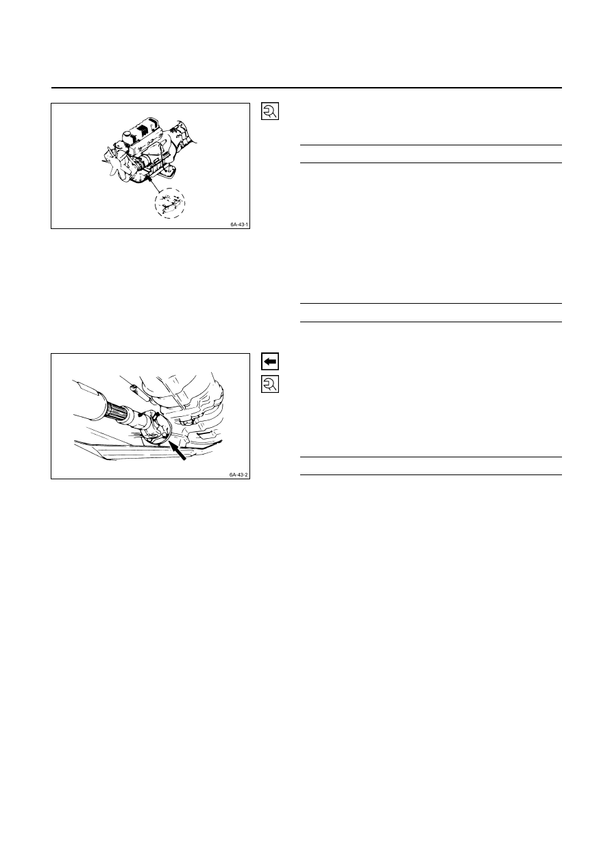
Front Propeller Shaft (For 4
×××× 4)
1. Connect the propeller shaft flange yoke to the
matching flange.
2. Tighten the propeller shaft flange yoke bolt to the
specified torque.
Propeller Shaft Flange Yoke Bolt
Torque kg·m
(lb.ft/N·m)
3.6
± 0.3 (26.0 ± 2.2/35.3 ± 2.9)
Note:
If the splined yoke and the front propeller shaft have
accidentally separated, align their setting marks and
recouple them.
Refer to “FRONT PROPELLER SHAFT REMOVAL.”
Нет комментариевНе стесняйтесь поделиться с нами вашим ценным мнением.
Текст