Isuzu D-Max / Isuzu Rodeo (TFR/TFS). Manual — part 27

4JA1-TC/4JH1-TC ENGINE DRIVEABILITY AND EMISSIONS
6E–103
44
P1650
A
ON
CAN Device Offline
CAN controller detects Bus-off
or canceling.
MAB (fuel cutoff solenoid
valve) is operated.
CAN controller detects correct Bus
signal.
1. CAN high circuit open, short to
ground or short to voltage circuit.
2. CAN low circuit open, short to
ground or short to voltage circuit.
3. Poor connector connection.
4. Electrical interference.
5. ECM malfunction.
6. PSG (pump control unit) mal-
function.
99/100
P1651(B)
B
ON
CAN Device Hang-up
CAN controller does not react
under engine running.
CAN controller reacts correctly
under engine running.
1. ECM malfunction.
2. PSG (pump control unit) mal-
function.
-
-
45
P1651
A
ON
CAN Malfunction (PSG)
The PSG (pump control unit)
does not recognize CAN sig-
nal from the CAN controller.
1. MAB (fuel cutoff solenoid
valve) is operated.
2. Desired injection quantity
becomes 0mg/strk.
The PSG (pump control unit) recog-
nizes CAN signal from the CAN
controller.
1. ECM malfunction.
2. PSG (pump control unit) mal-
function.
-
-
B
ON
CAN Receives Error
The ECM does not read CAN
signal from the PSG (pump
control unit).
The ECM reads CAN signal from
the PSG (pump control unit).
1. CAN high circuit open, short to
ground or short to voltage circuit.
2. CAN low circuit open, short to
ground or short to voltage circuit.
3. Poor connector connection.
4. Electrical interference.
5. ECM malfunction.
6. PSG (pump control unit) mal-
function.
99/100
P1650(A)
77
P1690
4
OFF
Check Engine Lamp (MIL) Circuit
Voltage Low
Check engine lamp circuit
open or short to ground circuit.
No fail-safe function.
Check engine lamp circuit is correct
condition.
1. Check engine lamp circuit
open or short to ground circuit.
2. Check engine lamp malfunc-
tion.
3. ECM malfunction.
42
B****
8
OFF
Check Engine Lamp (MIL) Circuit
Voltage High
Check engine lamp circuit
short to voltage circuit.
ECM malfunction.
-
-
Flash
Code
Code
Symptom
Code
MIL
DTC Name
DTC Setting Condition
Fail-Safe (Back Up)
Recovery Condition
Related Failure Parts
Related
ECM Pin
No.
Related
Multiple
DTC
4JA1
-TC
(MT)
4JH1
-TC
(MT)
4JH1
-TC
(AT)
6E–104
4JA1-TC/4JH1-TC ENGINE DRIVEABILITY AND EMISSIONS
DIAGNOSTIC TROUBLE CODE (DTC) P0100 (SYMPTOM CODE 7)
(FLASH CODE 65) MASS AIR FLOW (MAF) SENSOR VOLTAGE SUPPLY
CIRCUIT HIGH INPUT
DIAGNOSTIC TROUBLE CODE (DTC) P0100 (SYMPTOM CODE 9)
(FLASH CODE 65) MASS AIR FLOW (MAF) SENSOR VOLTAGE SUPPLY
CIRCUIT LOW INPUT
DIAGNOSTIC TROUBLE CODE (DTC) P0100 (SYMPTOM CODE B)
(FLASH CODE 65) MASS AIR FLOW (MAF) SENSOR OUTPUT CIRCUIT LOW
INPUT
DIAGNOSTIC TROUBLE CODE (DTC) P0100 (SYMPTOM CODE C)
(FLASH CODE 65) MASS AIR FLOW (MAF) SENSOR OUTPUT CIRCUIT HIGH
INPUT
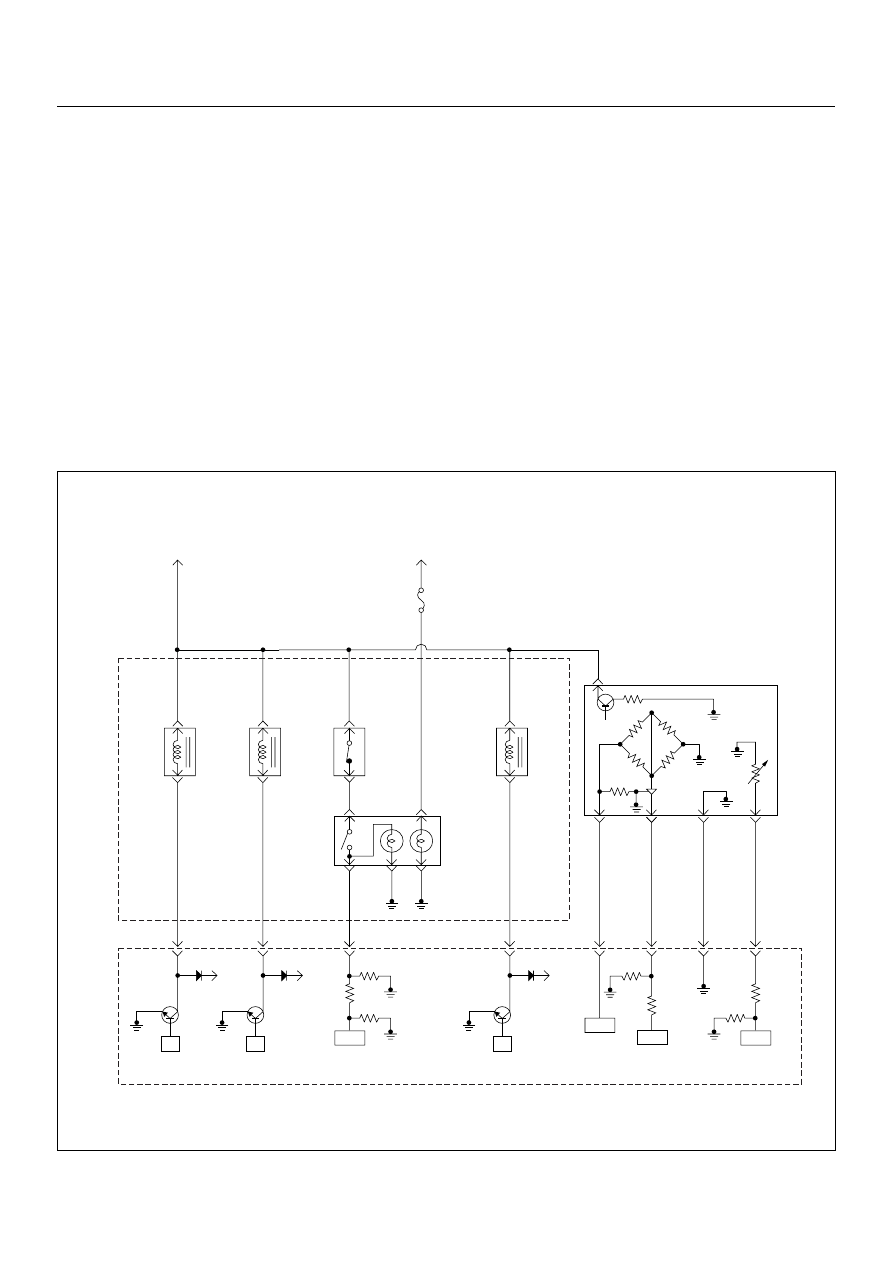
Batt
µP
Batt
µP
Batt
µP
0.5
BLK/
URG
0.5
BRN/
RED
0.5
BLU/
RED
0.5
BLU/
RED
4JA1-TC
0.5
GRY/
YEL
97
46
61
0.5
WHT/
RED
83
0.5
GRN/
RED
88
0.5
BLK/
RED
92
0.5
BLK/
BLU
84
IAT
Sensor
MAF &
IAT
Sensor
Rr Fog
Light
10A
EGR-
EVRV
0.5
WHT/
BLK
0.5
BLU/
RED
0.5
WHT/
BLU
0.5
BLU/
RED
0.5
GRN/
RED
0.5
BLU/
RED
Exhaust
Throttle
VSV2
Exhaust
Throttle
VSV1
Engine
Warming Up
SW
Thermo
SW
2
4
5
3
1
Battery
Voltage
ECM
Main Relay
IC
IC
IC
CPU
Engine
Control
Module
(ECM)
40

4JA1-TC/4JH1-TC ENGINE DRIVEABILITY AND EMISSIONS
6E–105
Condition for setting the DTC and action taken when the DTC sets
Circuit Description
The mass air flow (MAF) sensor is part of the intake air
system. It is fitted between the air cleaner and
turbocharger and measure the mass air flowing into the
engine.
The mass air flow (MAF) sensor element measures the
partial air mass through a measurement duct on the
sensor housing.
The ECM monitors the MAF sensor supply voltage and
MAF sensor output voltage. The supply voltage is out of
range, DTC P0100 (Symptom Code 7) or P0100
(Symptom Code 9) will be stored. The output voltage
excessively high or low, DTC P0100 (Symptom Code B)
or P0100 (Symptom Code C) will be stored.
Diagnostic Aids
An intermittent may be caused by the following:
• Poor connections.
• Misrouted harness.
• Rubbed through wire insulation.
• Broken wire inside the insulation.
Check for the following conditions:
• Poor connection at ECM-Inspect harness connectors
for backed out terminals, improper mating, broken
locks, improperly formed or damaged terminals, and
poor terminal to wire connection.
• Damaged harness-Inspect the wiring harness for
damage. If the harness appears to be OK, observe
the “Mass Air Flow” display on the Tech2 while
moving connectors and wiring harness related to the
sensor.
Diagnostic Trouble Code (DTC) P0100 (Symptom Code 7) (Flash Code 65)
Mass Air Flow (MAF) Sensor Voltage Supply Circuit High Input
Flash
Code
Code
Symptom
Code
MIL
DTC Name
DTC Setting Condition
Fail-Safe (Back Up)
65
P0100
7
ON
Mass Air Flow (MAF) Sensor
Voltage Supply Circuit High
Input
MAF sensor power supply
voltage is more than 5.2V.
ECM uses mass air flow
1600mg/strk & EGR 10% con-
ditions as substitute.
9
ON
Mass Air Flow (MAF) Sensor
Voltage Supply Circuit Low
Input
MAF sensor power supply
voltage is below 4.6V.
B
ON
Mass Air Flow (MAF) Sensor
Output Circuit Low Input
1. Engine speed is between
600rpm and 5000rpm.
2. MAF sensor output is below
-33.7mg/strk.
C
ON
Mass Air Flow (MAF) Sensor
Output Circuit High Input
1. Engine speed is between
600rpm and 5000rpm.
2. MAF sensor output is more
than 1784mg/strk.
Step
Action
Value(s)
Yes
No
1
Was the “On-Board Diagnostic (OBD) System Check”
performed?
—
Go to Step 2
Go to On Board
Diagnostic
(OBD) System
Check
2
1. Connect the Tech 2.
2. Review and record the failure information.
3. Select “F0: Read DTC Infor As Stored By ECU” in
“F0: Diagnostic Trouble Codes”.
Is the DTC P0100 (Symptom Code 7) stored as
“Present Failure”?
—
Go to Step 3
Refer to
Diagnostic Aids
and Go to Step
3
6E–106
4JA1-TC/4JH1-TC ENGINE DRIVEABILITY AND EMISSIONS
3
1. Using the Tech 2, ignition “On” and engine “Off”.
2. Select “F1: Clear DTC Information” in “F0:
Diagnostic Trouble Codes” with the Tech 2 and
clear the DTC information.
3. Operate the vehicle and monitor the “F0: Read
DTC Infor As Stored By ECU” in the “F0:
Diagnostic Trouble Codes”.
Was the DTC P0100 (Symptom Code 7) stored in this
ignition cycle?
—
Go to Step 4
Refer to
Diagnostic Aids
and Go to Step
4
4
Check for poor/faulty connection at the MAF sensor or
ECM connector. If a poor/faulty connection is found,
repair as necessary.
Was the problem found?
—
Verify repair
Go to Step 5
5
Visually check the MAF sensor.
Was the problem found?
—
Go to Step 11
Go to Step 6
6
Using the DVM and check the MAF sensor power
supply circuit.
1. Ignition “On”, engine “Off”.
2. Disconnect the MAF & IAT sensor connector.
3. Check the circuit for short to battery voltage
circuit.
Was the DVM indicated specified value?
Approximately
5.0V
Go to Step 11
Less than 1V:
Go to Step 7
More than
specified value:
Go to Step 8
7
Repair the open circuit between the ECM and MAF
sensor.
Was the problem solved?
—
Verify repair
Go to Step 8
Step
Action
Value(s)
Yes
No
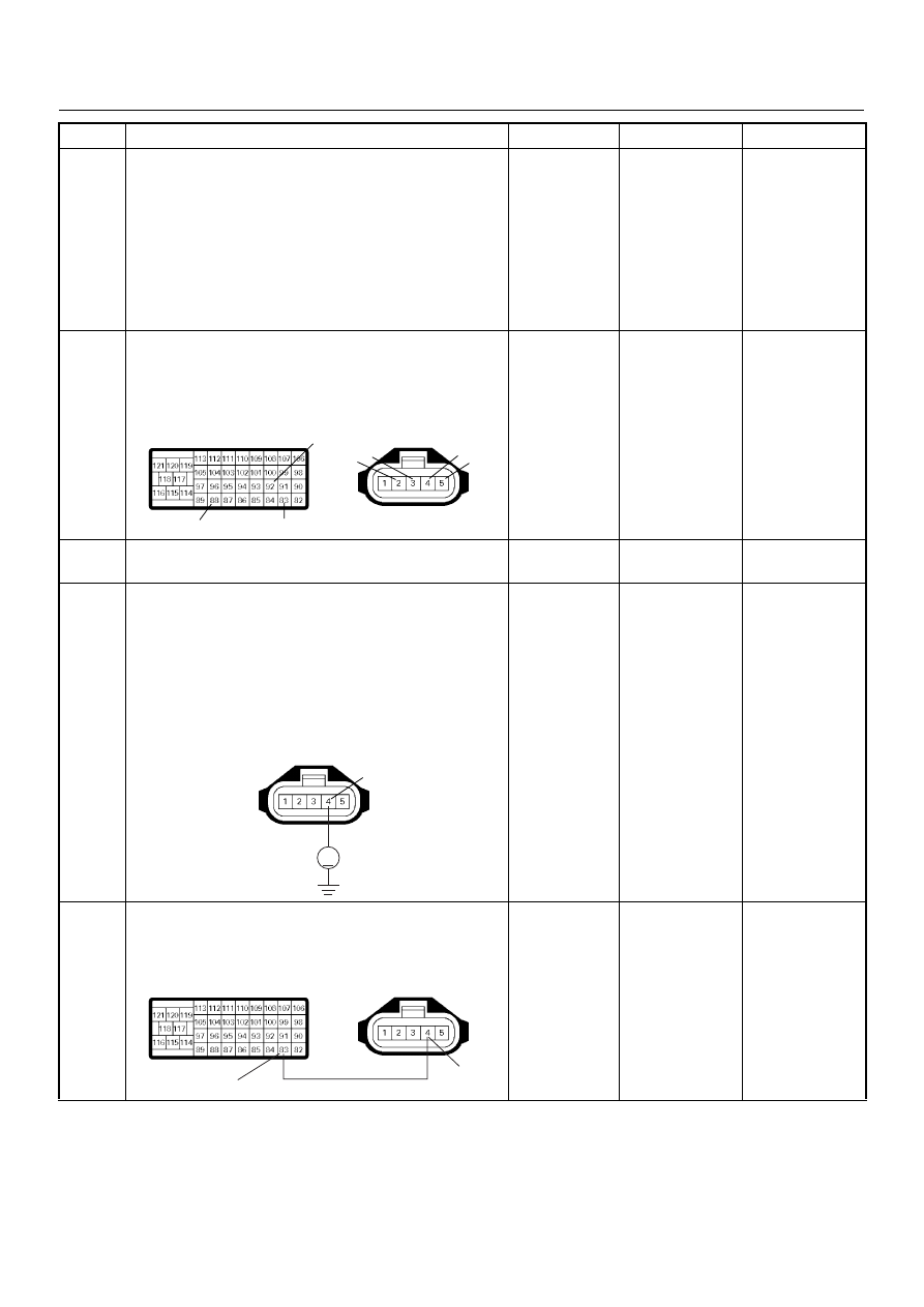
92
88
83
2 3
4
5
C-51
C-57(B)
V
4
C-51
83
4
C-51
C-57(B)
Нет комментариевНе стесняйтесь поделиться с нами вашим ценным мнением.
Текст