Isuzu D-Max / Isuzu Rodeo (TFR/TFS). Manual — part 1091
ELECTRICAL-BODY AND CHASSIS 8-121
Connector
Be absolutely sure that the lighting switch connector is securely
connected.
This will prevent a poor contact and an open circuit.
Wire Harness
Do not pinch the wire harnesses between the cluster and the
meter hood during the cluster installation procedure.
Wire damage will result.
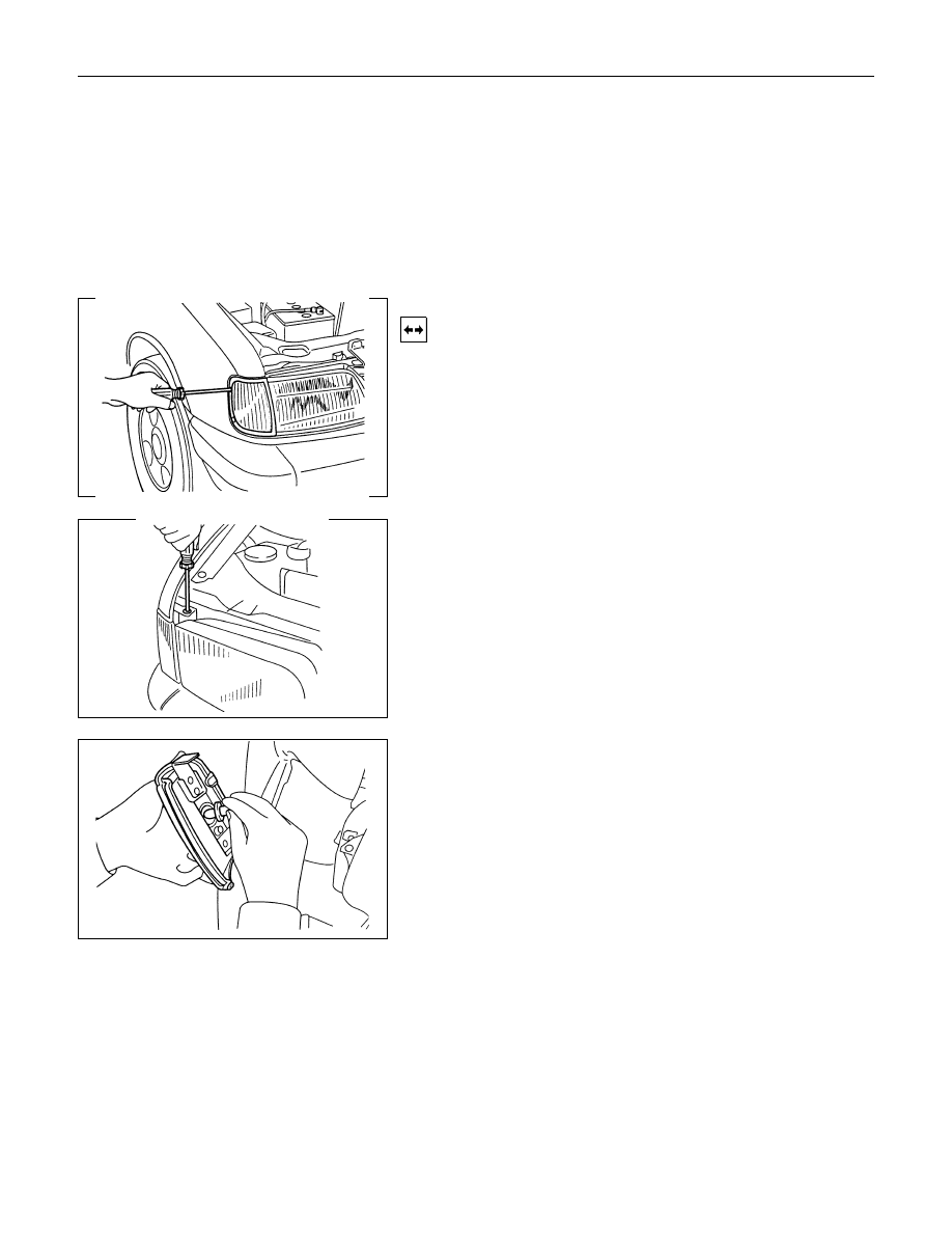
CLEARANCE LIGHT
Removal
1. Remove the radiator grille.
(Refer to headlight removal procedure.)
2. Remove the side screws.
3. Remove the top screw.
4. Turn the socket counterclockwise to disconnect it from the
clearance light housing.
5. Pull the bulb from the socket.
8-122 ELECTRICAL-BODY AND CHASSIS
Installation
Follow the removal procedure in the reverse order to install the
clearance light.
Pay close attention to the important points mentioned in the
following paragraphs.
Connector
Be absolutely sure that the clearance light connector is
securely connected.
This will prevent a poor contact and an open circuit.
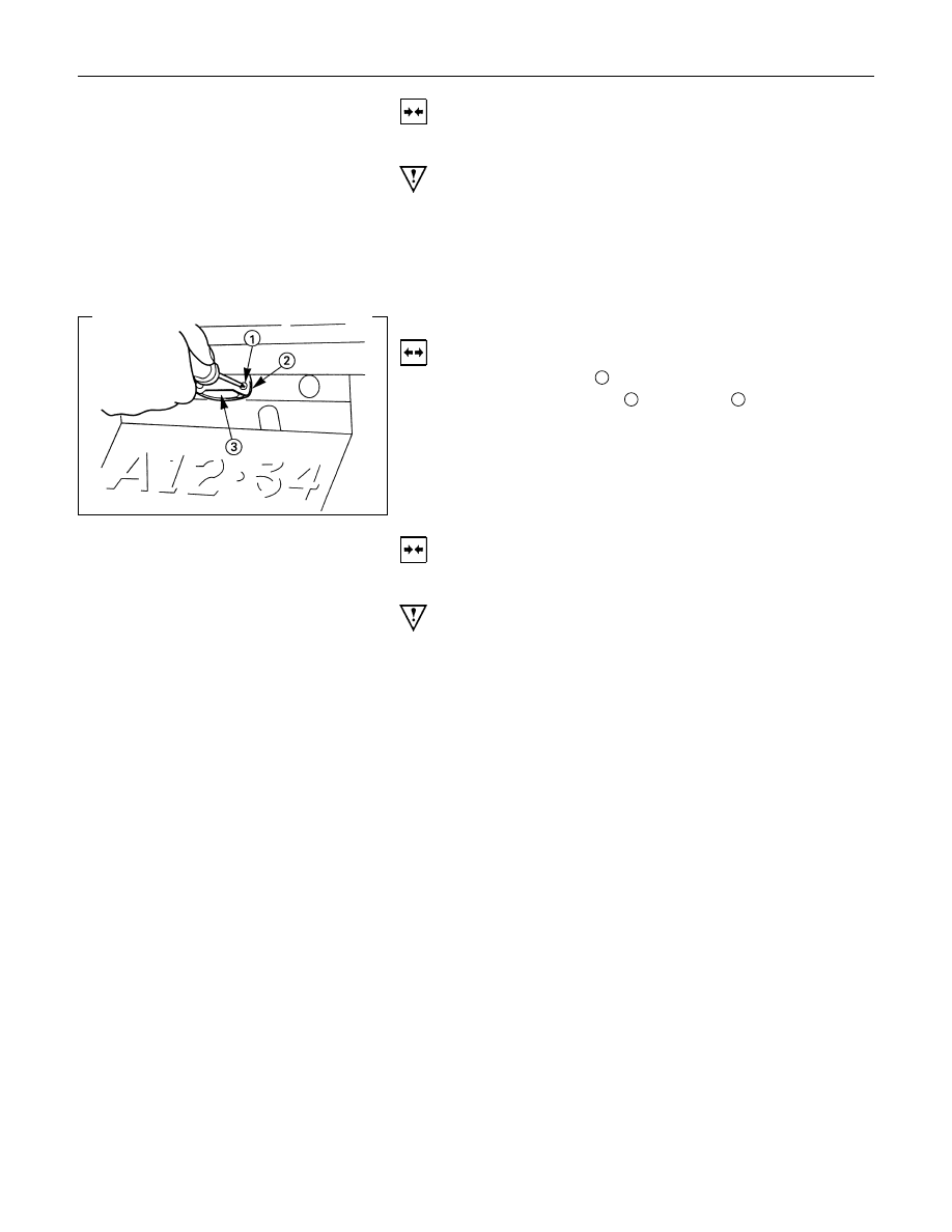
LICENSE PLATE LIGHT
Removal
1. Loosen the screws
1
.
2. Remove the lens cover
2
and the lens
3
.
3. Pull the bulb to remove it.
Installation
Follow the removal procedure in the reverse order to install the
license plate light.
Pay close attention to the important points mentioned in the
following paragraphs.
Bulb
Be absolutely sure that the license plate light bulb is correctly
installed.
This will prevent a poor contact and open circuit.

ELECTRICAL-BODY AND CHASSIS 8-123
HEADLIGHT BEAM SWITCH
(COMBINATION SWITCH)
Removal
1. Remove the screws on the lower part of the steering wheel.
2. Remove the horn pad.
3. Remove the wiring connector.
4. Remove the steering wheel fixing nuts.
5. Remove the steering wheel.
Refer to the "STEERING" Section of this manual.
6. Remove the Instrument panel lower cover.
7. Remove the steering column cover.
8. Disconnect the connector.
9. Remove the headlight beam switch (lever) from the steering
shaft (combination switch).
Installation
Follow the removal procedure in the reverse order to install the
headlight beam switch(lever).
Pay close attention to the important points mentioned in the
following paragraphs.
Connector
Be absolutely sure that the headlight beam switch connector is
securely connected.
This will prevent a poor contact and an open circuit.
Wire Harness
Do not pinch the wire harnesses between the cluster and the
meter hood during the cluster installation procedure.
Wire damage will result.
8-124 ELECTRICAL-BODY AND CHASSIS
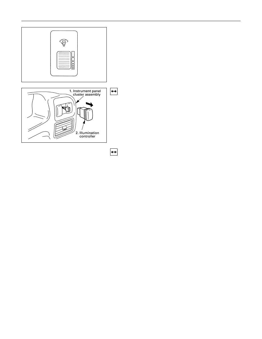
ILLUMINATION CONTROLLER
Turning the illumination controller knob upward increases the
brightness of each illumination light, turning it downward
decreases its brightness.
Removal
1. Instrument Panel Cluster Assembly
• Refer to Section 10 “BODY” for instrument panel cluster
assembly removal steps.
2. Illumination Controller
• Disconnect the switch connector.
• To remove the switch, push the lock from the back side
of the cluster assembly.
Installation
To install, follow the removal procedure in the reverse order.
Connector
Be absolutely sure that the illumination controller connector is
securely connected.
This will prevent a poor contact and an open circuit.
Нет комментариевНе стесняйтесь поделиться с нами вашим ценным мнением.
Текст