Isuzu D-Max / Isuzu Rodeo (TFR/TFS). Manual — part 671
7A1 – 184 AUTOMATIC TRANSMISSION (4L30-E)
1
8
13
27
10
9
7
6
15
14
12
11
19
18
16
17
26
25
23
24
4
5
3
21
22
2
20
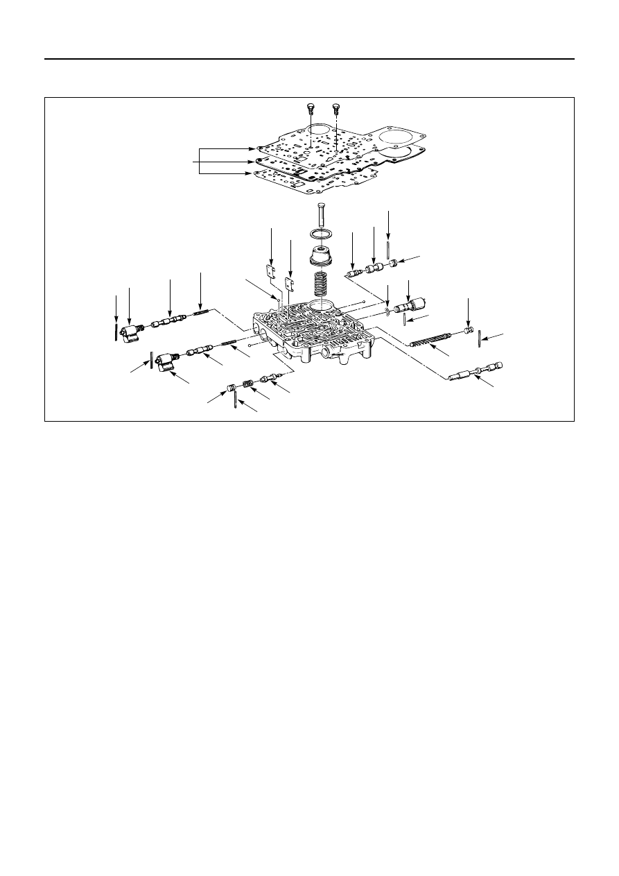
MAIN CASE VALVE BODY
Disassembly Steps
1. Gaskets and transfer plate
2. Manual valve
3. Band control solenoid
4. Pin
5. Waved washer
6. Spring pin
7. Solenoid A
8. Retainer
9. 1-2/3-4 shift valve
10. Spring
11. Spring pin
12. Solenoid B
13. Retainer
14. 2-3 shift valve
15. Spring
16. Spring pin
17. Plug
18. Spring
19. Low pressure control valve
20. Spring pin
21. Plug
22. Band control screen assembly
23. Spring pin
24. Plug
25. 1-2 accumulator valve
26. 1-2 accumulator control valve
27. Check ball
Reassembly Steps
To reassemble, follow the disassembly steps
in the reverse order.
AUTOMATIC TRANSMISSION (4L30-E) 7A1 – 185
DISASSEMBLY
1. Gaskets and Transfer Plate
Remove two 11mm bolts from valve body.
2. Manual Valve
3. Band Control Solenoid
4. Pin
5. Waved Washer
6. Spring Pin
7. Solenoid A
Remove solenoids by grasping the metal tip. Do not
grasp the connector housing.
8. Retainer
9. 1-2/3-4 Shift Valve
10. Spring
11. Spring Pin
12. Solenoid B
Remove solenoids by grasping the metal tip. Do not
grasp the connector housing.
13. Retainer
14. 2-3 Shift Valve
15. Spring
16. Spring Pin
17. Plug
18. Spring
19. Low Pressure Control Valve
20. Spring Pin
21. Plug
22. Band Control Screen Assembly
23. Spring Pin
24. Plug
25. 1-2 Accumulator Valve
26. 1-2 Accumulator Control Valve
27. Check Ball
Remove 1 check ball from valve body.
INSPECTION AND REPAIR
Inspect for the following and replace any damaged or
worn parts:
•
Damage or wear to each valve.
•
Damage in oil passeges.
•
Cracks or damage to valve body.
•
Valve operations.
•
Spring fatigue.

7A1 – 186 AUTOMATIC TRANSMISSION (4L30-E)
REASSEMBLY
27. Check Ball
Install 1 check ball to valve body
26. 1-2 Accumulator Control Valve
25. 1-2 Accumulator Valve
24. Plug
23. Spring Pin
22. Band Control Screen Assembly
21. Plug
20. Spring Pin
19. Low Pressure Control Valve
18. Spring
17. Plug
16. Spring Pin
15. Spring
14. 2-3 Shift Valve
13. Retainer
12. Solenoid B
11. Spring Pin
10. Spring
9. 1-2/3-4 Shift Valve
8. Retainer
7. Solenoid A
6. Spring Pin
5. Waved Washer
4. Pin
3. Band Control Solenoid
2. Manual Valve
1. Gaskets and Transfer Plate
1) Install gasket (valve body/transfer plate) and
transfer plate, using two guide pins.
2) Install two 11mm bolts.
Valve Body Bolt Torque
N·m (kg·cm / lb·in)
13 (130 / 113)
3) Install gasket (transfer plate/main case).
Guide pins: 5-8840-2270-0 (J-3387-2)
AUTOMATIC TRANSMISSION (4L30-E) 7A1 – 187
2
6
8
13
1
15
14
10
12
11
7
4
5
9
3
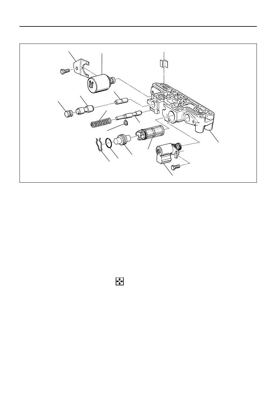
ADAPTER CASE VALVE BODY
DISASSEMBLY
1. Converter Clutch Solenoid
1) Remove 11mm bolt from valve body.
2) Remove converter control solenoid assembly with
two O-ring.
2. Retainer
Remove 11mm bolt and retainer from valve body.
3. Force Motor Solenoid
4. Retainer
5. Plug
6. 3/4 Accumulator Valve
7. 3/4 Accumulator Control Valve
Disassembly Steps
1. Converter clutch solenoid
2. Retainer
3. Force motor solenoid
4. Retainer
5. Plug
6. 3/4 accumulator valve
7. 3/4 accumulator control valve
8. Spring
9. Retaining ring
10. Feed limit valve
11. Plug retainer
12. O-ring
13. Plug
14. Force motor screen assembly
15. Adapter case valve body
Reassembly Steps
To reassemble, follow the disassembly steps
in the reverse order.
243RW001
Нет комментариевНе стесняйтесь поделиться с нами вашим ценным мнением.
Текст