Isuzu D-Max / Isuzu Rodeo (TFR/TFS). Manual — part 669

7A1 – 176 AUTOMATIC TRANSMISSION (4L30-E)
2. O-ring
1. Torque converter
3. Mode switch
and transmission
harness
6. Adapter case
valve body
5. Wiring harness
4. Adapter case
oil pan
8. Oil filter
7. Main case oil pan
12.Main
case
valve
body
9. Manual detent
11. Servo cover
10. Wiring harness
鈴木
'97/ 11/ 28
発注者
発注日
10012
作業番号
240LW003
AUTOMATIC TRANSMISSION (4L30-E) 7A1 – 177
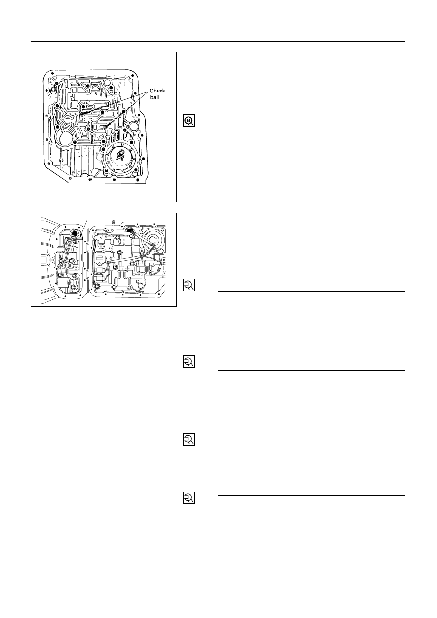
12. Main Case Valve Body and Ground Wire
1) Install two check balls.
2) Inspect electrical connector and seal, replace if
necessary.
3) Install electrical 4 pin connector/main case and
wiring harness.
4) Install two guide pins into main case.
Guide pin: 5-8840-0022-0 (J-25025-B)
5) Install valve body complete assembly and manual
valve link.
NOTE:
Valve must be extended as the short end of manual
valve link is connected to the range selector lever.
Long end of link goes into valve.
6) Install seven 13 mm screws.
7) Pass ground wire of adapter case wiring harness
assembly through the hole joining adapter fluid
area and main case fluid area.
8) Assemble 8.5 mm connector of ground wire under
the head of this valve body bolt and reinstall it.
Main Case Valve Body
Bolt Torque
N·m (kg·m / lb·ft)
20 (2.0 / 15)
9) Remove two guide pins.
11. Servo Cover
Install servo cover gasket, cover and four 13 mm
screws.
Servo Cover Bolt Torque
N·m (kg·m / lb·ft)
25 (2.5 / 18)
10. Wiring Harness
Connect harness to band control and shift solenoids.
9. Manual Detent
Install roller and spring assembly with clip.
Install two 13 mm screws.
Manual Detent Screw Torque
N·m (kg·m / lb·ft)
20 (2.0 / 15)
8. Oil Filter
Install oil filter, three 13 mm screws.
Oil Filter Bolt Torque
N·m (kg·m / lb·ft)
20 (2.0 / 15)
Earth harness
244RV001

7A1 – 178 AUTOMATIC TRANSMISSION (4L30-E)
7. Main Case Oil Pan
Install oil pan gasket, magnet, oil pan, sixteen 10 mm
screws.
Main Case Oil Pan Bolt Torque
N·m (kg·cm / lb·in)
11 (110 / 96)
6. Adapter Case Valve Body
1) Inspect electrical connector and seal. Replace if
necessary.
Install electrical five pin connector and harness
assembly in bottom of adapter case.
Install gasket, transfer plate, gasket.
2) Install adapter case valve body complete and
seven 13 mm screws.
Adapter Case Valve Body
Bolt Torque
N·m (kg·m / lb·ft)
20 (2.0 / 15)
5. Wiring Harness
1) Connect harness assembly to converter clutch
solenoid, and force motor.
4. Adapter Case Oil Pan
1) Install oil pan gasket, oil pan, twelve 10 mm
screws.
Adapter Case Oil Pan
Bolt Torque
N·m (kg·cm / lb·in)
11 (110 / 96)
2) Rotate transmission, with bottom pan facing
down.

3. Mode Switch
1) Install mode switch, shield and two 10 mm
screws.
2) Adjust using setting tool.
Refer to “MODE SWITCH” in this section.
Selector Shaft Nut Torque
N·m (kg·m / lb·ft)
23 (2.3 / 17)
Mode Switch Screw Torque
N·m (kg·cm / lb·in)
13 (130 / 113)
2. O-Ring
Install O-ring on turbine shaft.
1. Torque Converter
1) The converter assembly must be replaced under
any of the following conditions:
a. Evidence of damage to the pump assembly
b. Metal particles are found after flushing the
cooler lines
c.
External leaks in hub weld area
d. Converter Pilot broken, damaged or poor fit
into crankshaft
e. Converter hub scored or damaged
f.
Internal failure in stator
g. Contamination from engine coolant
h. Excess end play
2) Install converter assembly.
Rotate transmission, bell housing up. Spin
converter to insure proper fit.
3) Fill transmission through the overfill screw, using
DEXRON
-III ATF.
AUTOMATIC TRANSMISSION (4L30-E) 7A1 – 179
Нет комментариевНе стесняйтесь поделиться с нами вашим ценным мнением.
Текст