Isuzu D-Max / Isuzu Rodeo (TFR/TFS). Manual — part 1771
DIAGNOSIS 7A2-135
No. G4: Large Noise During Idling with the Vehicle in Stop State
Description:
•
The transmission is noisy during the idling speed in all ranges.
Diagnosis Hints:
•
Causes such as solenoid operating sound or faulty oil pump are considered.
•
Distinguishing to some extent is possible by stopping the solenoid operation temporarily, checking the correlation
for the former case and, changing the line pressure and confirming the correlation with noise.
•
As a matter of course, noise may be generated around the engine, for instance, other than the AT and should be
checked carefully.
Note:
When the noise is generated only at the time of gear shift, it may be the sound of flowing ATF or gear
noise. If the sound varies depending on the gear speed to be shifted, it may be the gear noise generated
from the planetary gear and its related components. If the sound varies depending on the vehicle
speed, it may be the gear noise of the output system, and if varying depending on the engine speed, it
may be the gear noise of the input system or faulty torque converter.
In either case, sound may be "noise" depending on the origin and resonance object. When the object
generating the sound (resonance object) and the sound source (vibration source) are different,
investigation of the cause may be difficult.
No. H1: Judder Occurs at the Lock-up
Diagnosis Hints:
・The vehicle body judders at lock-up.
Diagnosis Hints:
・Slip due to burning of the lockup piston or insufficient fastening due to dropped working pressure are considered.
Trouble diagnosis flow is basically the same as "No. I1: No lock-up".
Note:
When the lock-up piston has burnt, foreign material mixed in the oil cooler is considered. In such a
case, inspect the oil cooler circuit for clogging of the oil cooler.
No. H2: Large Lock-up Shock
No. H3: Lock-up Point is High or Low
Description:
•
Large shock is felt at lock-up.
•
Lock-up point is excessive high or low.
Diagnosis Hints:
•
Out of properties of input sensor or faulty lock-up piston pressure system are considered.
•
Trouble diagnosis flow is basically the same as "No. I1: No lock-up".

7A2-136 DIAGNOSIS
No. I1: No Lock-up
Description:
•
Lockup is not performed in spite of the lock-up area.
Diagnosis:
•
Lockup is not performed in spite of the lock-up area.
•
Monitor the signal to the lock-up solenoid while carrying out a running test.
•
When the output signal to the lock-up solenoid is correctly sent causing no lock-up, clogged lock-up solenoid oil
passage or malfunction of the lock-up piston may be considered.
•
Even the lock-up area, the output signal to the lock-up solenoid is not sent, fault of the ATF thermo sensor
controlling the lockup is considered. (Lock-up is not operated at ATF temperature less than 11
°C or more than
128
°
C.)
Note:
When the lock-up piston has burnt, foreign material mixed in the oil cooler is considered. In such a
case, inspect the oil cooler circuit for clogging of the oil cooler
Possible Cause:
•
ATF thermo sensor detects low oil temperature (Lock-up is prohibited temperature less than 10
°
C.).
•
Clogged oil passage of lock-up duty solenoid.
•
Trouble in control valve body (faulty operation, sticking, clogged oil passage).
Step
Action
Yes
No
1
Are any DTCs stored?
Go to DTC Chart
Go to Step 2
2
Are the quantity, contamination and smell normal?
If the ATF level is
low, replenish up to
the specified level.
Go to Step 3
If ATF is extremely
black and
contaminated and
smells burnt, slip of
the clutch is
supposed.
Overhaul the AT
unit.
DIAGNOSIS 7A2-137
Step
Action
Yes
No
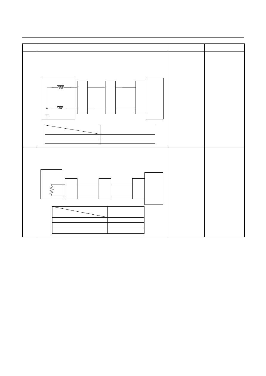
3
Inspection of electrical or mechanical fault
When the ATF oil temperature is above 20
°
C and the vehicle
speed is 80km/h, is ON signal issued to the lock-up solenoid
using the Tech 2 or circuit tester?
Control Valve
TCM
B17
B23
BLK
Lock-up Solenoid
Terminal
Assembly
VIO
Line Pressure Solenoid
E54
(4)
(6)
H23
(14)
(6)
C95
(17)
(23)
BLK
VIO
TCM terminal
Lock-up
B17
At lock-up
Approx. 7.2 V (AC range)
At unlock-up
Approx. 4.0 V (AC range)
Clogged oil
passage of lock-up
solenoid or faulty
operation of lock-
up piston.
Go to Step 4
4
Inspection of ATF oil thermo sensor.
Is the ATF oil temperature sensor terminal voltage correct?
After running using the Tech 2 data display function, is the ATF
temperature higher than 10
°
C?
ATF
Temp.
Sensor
TCM
B4 (+)
B14 (-)
H23
(8)
(3)
C95
(4)
(14)
BLU
Terminal
Assembly
BLU/BLK
E54
(2)
(8)
BLU
BLU/BLK
T C M te r m in a l
Te m p e r a tu r e
B 4
( O u tp u t v o lta g e )
2 0
1 .5 5
4 0
1 .0 8
6 0
0 .7
Monitor the electric
system input
sensor signal and
find a signal
causing no lockup.
Repair the defect or
replace.
7A2-138 DIAGNOSIS
No. J1: Oil Leaks from Breather
Description:
•
Oil leaks from breather.
Possible Cause:
•
ATF quantity is excessively.
No. J2: Oil Leaks Between Engine and Converter Housing
No. J3: Oil Leaks Between Main Case and Converter Housing
No. J4: Oil Leaks Between Main Case and Rear Housing
No. J5: Oil Leaks from Oil Pan
No. J6: Oil Leaks from Manual Shaft Oil Seal
No. J7: Oil Leaks from Oil Cooler Pipe Joint
Description:
•
Oil leaks between engine and converter housing.
•
Oil leaks between converter housing and main case.
•
Oil leaks between main case and rear housing.
•
Oil leaks from oil pan.
•
Oil leaks from manual shaft oil seal.
•
Oil leaks from oil cooler pipe joint.
Possible Cause:
•
Faulty oil seal or sealing of contact surface is considered.
No. Z1: Transmission Overheat
Description:
•
You smell the transmission burning.
•
The transmission smokes.
Possible Cause:
•
Slip
of
clutch.
If slip of clutch is caused, a DTC (gear ratio error) is stored.
•
Clogged oil cooler (foreign substance mixed)
•
ATF stirred excessively (too much ATF).
•
Faulty torque converter operating pressure.
•
Faulty lock-up piston.
Нет комментариевНе стесняйтесь поделиться с нами вашим ценным мнением.
Текст