Isuzu D-Max / Isuzu Rodeo (TFR/TFS). Manual — part 1770
DIAGNOSIS 7A2-131
Step
Action
Yes
No
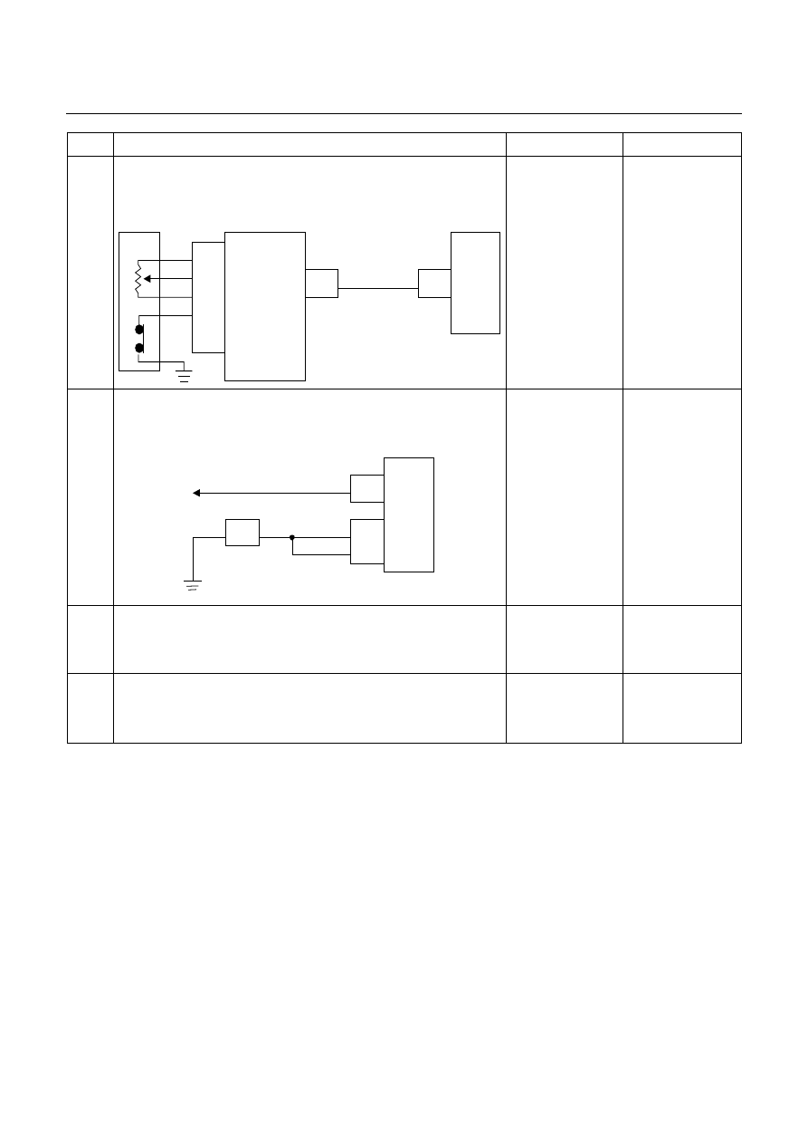
6
Inspect the output voltage and throttle opening signal of the
throttle position sensor using a Tech 2 or circuit tester.
Is a voltage value in proportion to the throttle opening output?
TPS
TCM
A16
C56
(28)
C94
(16)
RED/WHT
C56
(49)
(38)
(57)
(69)
ECM
A47 (GND)
A35 (Output)
A26
A55 (+5V)
A69 (Idle SW)
Go to Step 7
Repair the defect or
replace.
7
Check of power supply to and earth of TCM.
Are the power supply and earth proper?
TCM
A1 (+B)
B5
B15
H23
(15)
C95
(5)
(15)
BLK/YEL
BLK
BLK
Battery
C94
(1)
BLK
Go to Step 8
Check the power
source harness and
earth harness (bolt
tightening to the
body).
8
Is the stall revolution correct in D, 3, 2 and L range? Refer the
STALL TEST section in this manual.
Go to Step 6
Repair the defect or
replace.
9
Is the line pressure correct? Refer the LINE PRESSURE TEST
section in this manual.
Trouble in the AT
assembly or control
valve.
Repair the defect or
replace.
7A2-132 DIAGNOSIS
No. F2: Engine Races Up During Acceleration (Slip)
Description:
•
The engine speed up when the accelerator pedal is stepped on for acceleration and the gear is shifted up or
down.
•
Only the engine speeds up but vehicle speed does not increase when the accelerator pedal is stepped on for
acceleration during the running.
Diagnosis Hints:
•
Basically same causes as "No. C1 - C8: Engine races up (slip) by shift up or shift down" are considered.
When the condition of No. C1-C8 grows worse, symptom of No. F2 results.
No. F3: Noise or Vibration During the Running in R, D, 3, 2 or L Range
Description:
•
Noise or vibration is generated in the vicinity of AT during the running.
Diagnosis Hints:
•
Cause other than AT can be also considered. It is effective means to reproduce a running condition using a lift
up, chassis dynamo, etc. to investigate the origin (generating condition) of noise and vibration.
Caution:
Lifting up some unit to test it accompanies danger. Provide safety measures as far as possible and
carry out the test with sufficient care.
Possible Cause:
Following sources of noise or vibration other than the AT can be considered.
•
Noise from differential gears.
•
Noise from propeller shaft.
•
The bearing support in the middle of the propeller shaft has fatigued, and the bend angle of the propeller shaft
has changed, causing vibration at the time of start.
•
Unbalanced and poor uniformity of tires cause vibration.
No. F4: Engine Brake Does Not Apply in L Range
Description:
•
The engine brake does not apply, allowing the vehicle to run freely when the accelerator pedal is released at low
speed in L range.
Possible Cause:
•
Slip of clutch (low & reverse brake)
If slip of clutch is caused, a DTC (gear ratio error) is stored.
•
Faulty input/output signal system.
Low & reverse brake duty solenoid
•
Faulty control valve (faulty operation, sticking).
DIAGNOSIS 7A2-133
No. F5: Engine Stalls Before Vehicle Stops from Running
Description:
•
The engine stalls simultaneously with the vehicle stop when the brake pedal is stepped on to stop the vehicle
during the running.
Possible Cause:
•
Trouble on the engine system side (fuel injection control, engine speed control, etc.) is considered.
•
Refer
to
"No. B5: Engine stalls when selecting from N range to R, D, 3, 2 or L range".
No. G1: Vehicle Moves in P Range or Parking Gear is Not
Disengaged other than P Range
Description:
•
Vehicle moves though it stops at a slope and P range is selected.
•
The engine stalls and vehicle does not move though other than P range is selected and the accelerator pedal is
stepped on.
Possible Cause:
•
Trouble of the parking mechanism (noise or shock may result).
•
Disordered selector cable (only when traveling in the P range).
•
If the vehicle moves in the N range, follow the procedure of "No. B1: Vehicle runs in N range".
No. G2: Creep Force is Large
Description:
•
Vehicle accelerates in D, 3, 2, L, and R ranges though the accelerator pedal is not stepped on.
Possible Cause:
•
Too high engine idling speed (not attributable to AT).

7A2-134 DIAGNOSIS
No. G3: Creep Force is small
Description:
•
Vehicle does not move though a run range is selected on a flat road during the idling.
Diagnosis Hints:
•
When the creep force is small in all ranges, low engine output is considered. Another possible cause is slip of
clutch. If the creep is normal only in the R range, operation of the fail-safe function due to a trouble in the electrical
system is considered.
Possible Cause:
•
Slip of clutch (low clutch).
If slip of clutch is caused, a DTC (gear ratio error) is stored.
•
Low engine output (low idling speed, out of injection timing, lowered compression pressure, etc.).
•
Shortage or faulty quality of ATF.
•
Disconnection or short circuit of solenoid valve output.
•
Clogged oil passage of solenoid valve output.
•
Faulty ground return line in AT assembly.
If the ground return line earth is faulty, clutch pressure may decrease causing slip of the clutch.
•
Trouble in the torque converter system (faulty operation).
Step
Action
Yes
No
1
Gear ratio trouble diagnosis.
Travel in the following sequence for about 7 seconds or
more in each range: Start in the L range (1st) to 2 range
(2nd) to 3 range (3rd) to D range (4th) (to detect the gear
ratio trouble exactly, this process should be carried out)
Go to Step 2
Go to Step 2
2
Are any DTCs stored?
Go to DTC Chart
Go to Step 3
3
Are the quantity, contamination and smell normal?
If the ATF level is low,
replenish up to the
specified level.
Go to Step 4
If ATF is extremely
black and
contaminated and
smells burnt, slip of the
clutch is supposed.
Overhaul the AT unit.
4
Are the idling speed and other engine system normal?
Go to Step 5
Repair the defect or
replace.
5
Is the stall revolution normal in D, 3, 2 and L range? Refer
the STALL TEST section in this manual.
Go to Step 6
Repair the defect or
replace.
6
Is the line pressure normal? Refer the LINE PRESSURE
TEST section in this manual.
Trouble in the AT
assembly or control
valve.
Repair the defect or
replace.
Нет комментариевНе стесняйтесь поделиться с нами вашим ценным мнением.
Текст