Isuzu D-Max / Isuzu Rodeo (TFR/TFS). Manual — part 848
6E–121
3.2L ENGINE DRIVEABILITY AND EMISSIONS
DTC P0134 –HO2S Circuit Insufficient Activity
(Cont'd)
Step
No
Yes
Value(s)
Action
8
1. Ignition “OFF.”
2. With the ECM disconnected, check continuity of the
HO2S low circuit.
3. If the HO2S low circuit measures over 5 ohms,
repair open or poor connection as necessary.
Was a HO2S low circuit problem found and corrected?
—
Verify repair
Go to
Step 9
9
1. Ignition “ON,” engine “OFF.”
2. Disconnect HO2S and jumper the HO2S high and
low circuits (ECM side) to ground.
3. Using a Tech 2, monitor Bank 1 HO2S 1 voltage.
Is HO2S voltage in the specified range?
0-10 mV
Go to
Step 10
Go to
Step 11
10
Replace HO2S.
Is the action complete?
—
Verify repair
—
11
Replace the ECM.
Is the action complete?
—
Verify repair
—
6E–122 3.2L ENGINE DRIVEABILITY AND EMISSIONS
Diagnostic Trouble Code (DTC) P0171 (Flash DTC=44) Fuel Trim System Too
Lean
060RW054
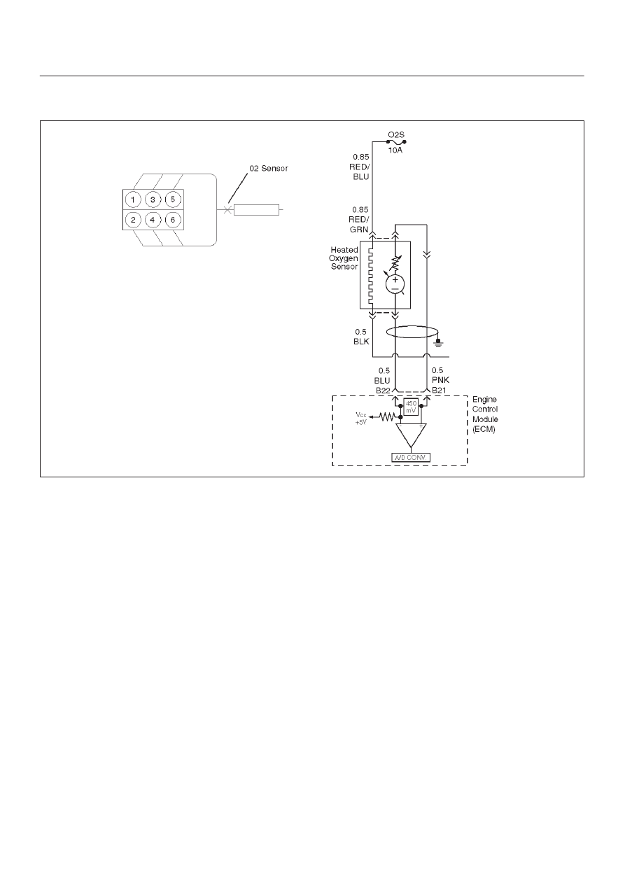
Circuit Description
To provide the best possible combination of driveability,
fuel economy, and emission control, a “closed loop”
air/fuel metering system is used. While in “closed loop,”
the Engine Control Module ECM monitors the HO2S
signals and adjusts fuel delivery based upon the HO2S
signal voltages. A change made to fuel delivery will be
indicated by the long and short term fuel trim values which
can be monitored with a Tech 2. Ideal fuel trim values are
around 0%; if the HO2S signals are indicating a lean
condition the ECM will add fuel, resulting in fuel trim
values above 0%. If a rich condition is detected, the fuel
trim values will be below 0%, indicating that the ECM is
reducing the amount of fuel delivered. If an excessively
lean condition is detected, the ECM will set DTC P0171.
The ECM’s maximum authority to control long term fuel
trim allows a range between –15% (automatic
transmission) or –12% (manual transmission) and +20%.
The ECM monitors fuel trim under various engine
speed/load fuel trim cells before determining the status
the fuel trim diagnostic.
Conditions for Setting the DTC
D
No Tech 2 test is being run.
D
Engine coolant temperature is between 35
°
C and
120
°
C.
D
No DTCs.
D
Intake air temperature is below 50
°
C.
D
Barometric pressure is more than 20 kpa.
D
Engine speed more than 600 RPM.
D
Fuel system is in “closed loop.”
D
Canister purge duty cycle is greater than 0% if on.
Action Taken When the DTC Sets
D
The ECM will illuminate the malfunction indicator lamp
(MIL) after the second consecutive trip in which the
fault is detected.
D
The ECM will store conditions which were present
when the DTC was set as Freeze Frame and in the
Failure Records data.
Conditions for Clearing the MIL/DTC
D
The ECM will turn the MIL “OFF” on the third
consecutive trip cycle during which the diagnostic has
been run and the fault condition is no longer present.
D
A history DTC P0171 will clear after 40 consecutive
warm-up cycles have occurred without a fault.
D
DTC P0171 can be cleared by using the Tech 2 “Clear
Info” function or by disconnecting the ECM battery
feed.
Diagnostic Aids
Check for the following conditions:
D
Poor connection at ECM – Inspect harness connectors
for backed-out terminals, improper mating, broken
6E–123
3.2L ENGINE DRIVEABILITY AND EMISSIONS
locks, improperly formed or damaged terminals, and
poor terminal-to-wire connection.
D
Damaged harness – Inspect the wiring harness for
damage. If the harness appears to be OK, observe the
HO2S display on the Tech 2 while moving connectors
and wiring harnesses related to the engine harness.
A change in the display will indicate the location of the
fault.
Reviewing the Failure Records vehicle mileage since the
diagnostic test last failed may help determine how often
the condition that caused the DTC to be set occurs. This
may assist in diagnosing the condition.
Test Description
Number(s) below refer to the step number(s) on the
Diagnostic Chart.
2. DTCs other than P0171 may indicate a condition
present which may cause a lean condition. If this is
the case, repairing the condition which caused the
other DTC will most likely correct the DTC P0171.
4. If the DTC P0171 test passes while the Failure
Records conditions are being duplicated, the lean
condition is intermittent. Refer to
Diagnostic Aids or
Symptoms for additional information on diagnosing
intermittent problems.

6E–124 3.2L ENGINE DRIVEABILITY AND EMISSIONS
DTC P0171 –Fuel Trim System Lean
Step
Action
Value(s)
Yes
No
1
Was the “On-Board Diagnostic (OBD) System Check”
performed?
—
Go to
Step 2
Go to
OBD
System
Check
2
Are any DTCs set other than P0171?
—
Go to the
applicable
DTC charts
and repair the
other DTCs
before
proceeding
with this chart
Go to
Step 3
3
1. Start the engine and operate the vehicle in “closed
loop.”
2. Observe the “Long Term Fuel Trim” display on the
Tech 2.
Is the displayed value greater than the specified value?
L.T. Fuel
Trim: +20%
Go to
Step 5
Go to
Step 4
4
1. Review and record the Tech 2 Failure Records data.
2. Clear the DTC P0171 and operate the vehicle to
duplicate the Failure Records conditions.
3. Monitor the Tech 2 “DTC” info for DTC P0171 while
operating the vehicle to duplicate the Failure
Records conditions.
4. Continue operating the vehicle until the DTC P0171
test runs and note the test result.
Does the Tech 2 indicate DTC P0171 failed this
ignition?
—
Go to
Step 5
The lean
condition is
not present.
If a
driveability
symptom still
exists, refer
to
Symptoms
section.
5
Was DTC oter than DTC P0171 also set?
—
Go to
Step 6
Go to
Step 15
6
Visually and physically inspect the vacuum hoses for
disconnects, splits, kinks, improper routing and
improper connections and repair any problem found.
Did your inspection reveal a problem requiring repair?
—
Verify repair
Go to
Step 7
7
Visually and physically inspect the crankcase
ventilation valve for proper installation and repair any
problem found (refer to
Crankcase Ventilation
System).
Did your inspection reveal a problem requiring repair?
—
Verify repair
Go to
Step 8
8
1. Inspect the MAF sensor inlet screen for damage or
for the presence of foreign objects which may
partially block the air flow sample through the MAF
sensor.
2. Correct any problem that is found as necessary.
Did your inspection of the MAF sensor reveal a
condition requiring repair?
—
Verify repair
Go to
Step 9
9
Start the engine and note the idle quality.
Is a high or unsteady idle being experienced?
—
Go to
Step 10
Go to
Step11
10
1. Visually and physically inspect the throttle body,
intake manifold for vacuum leaks.
2. Repair any vacuum leaks as necessary.
Did your inspection reveal a vacuum leak?
—
Verify repair
Go to
Step 11
Нет комментариевНе стесняйтесь поделиться с нами вашим ценным мнением.
Текст