Isuzu D-Max / Isuzu Rodeo (TFR/TFS). Manual — part 960
4C1-10 FRONT WHEEL DRIVE
FRONT HUB AND DISC (4
×
4 model)
FRONT WHEEL DRIVE 4C1-11
LOCKING HUB
AUTOMATIC TYPE
MANUAL TYPE
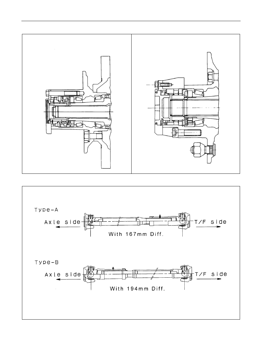
FRONT PROPELLER SHAFT
4C1-12 FRONT WHEEL DRIVE
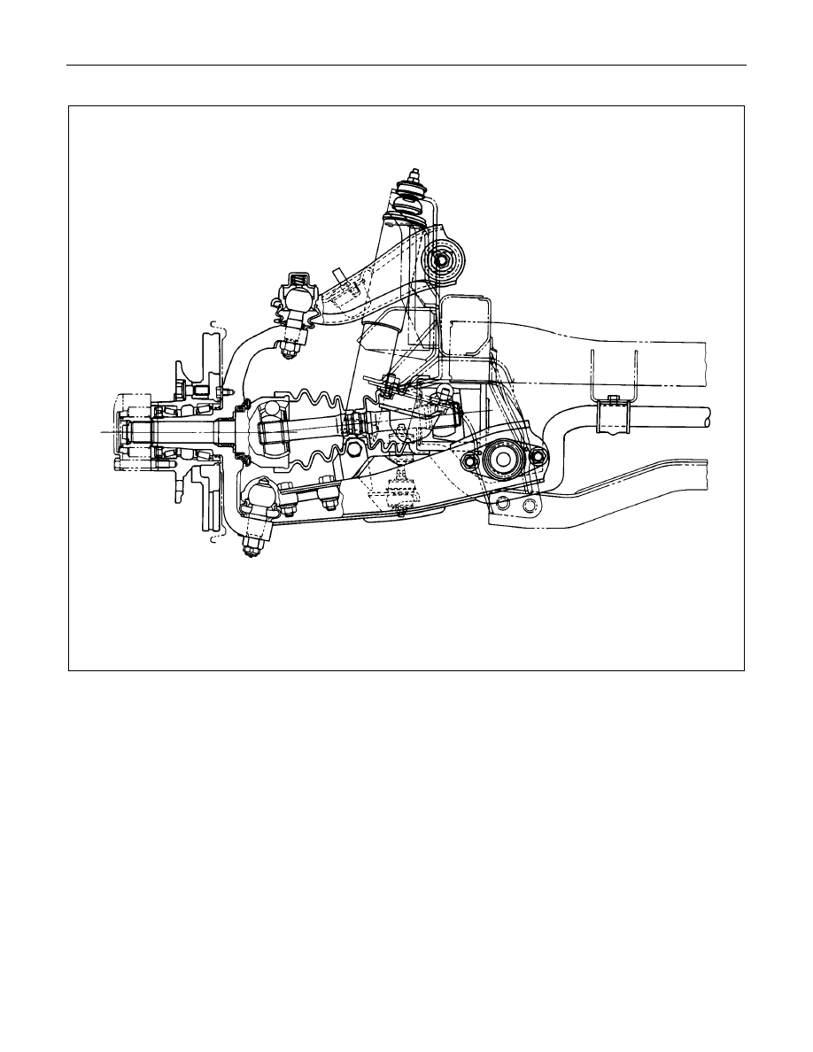
FRONT DRIVE AXLE ASSEMBLY
REMOVAL AND INSTALLATION
1. Refer to SECTION 3E “WHEEL AND TIRES” for road wheel Disassembly and Reassembly procedure.
2. Refer to SECTION 4 “BRAKES” for disc brake caliper removal and installation procedure.
3. Refer to SECTION 3B “STEERING” for Steering linkage removal and installation procedure.
4. Refer to SECTION 4C “FRONT WHEEL DRIVE” for automatic hub disassembly and reassembly procedure.
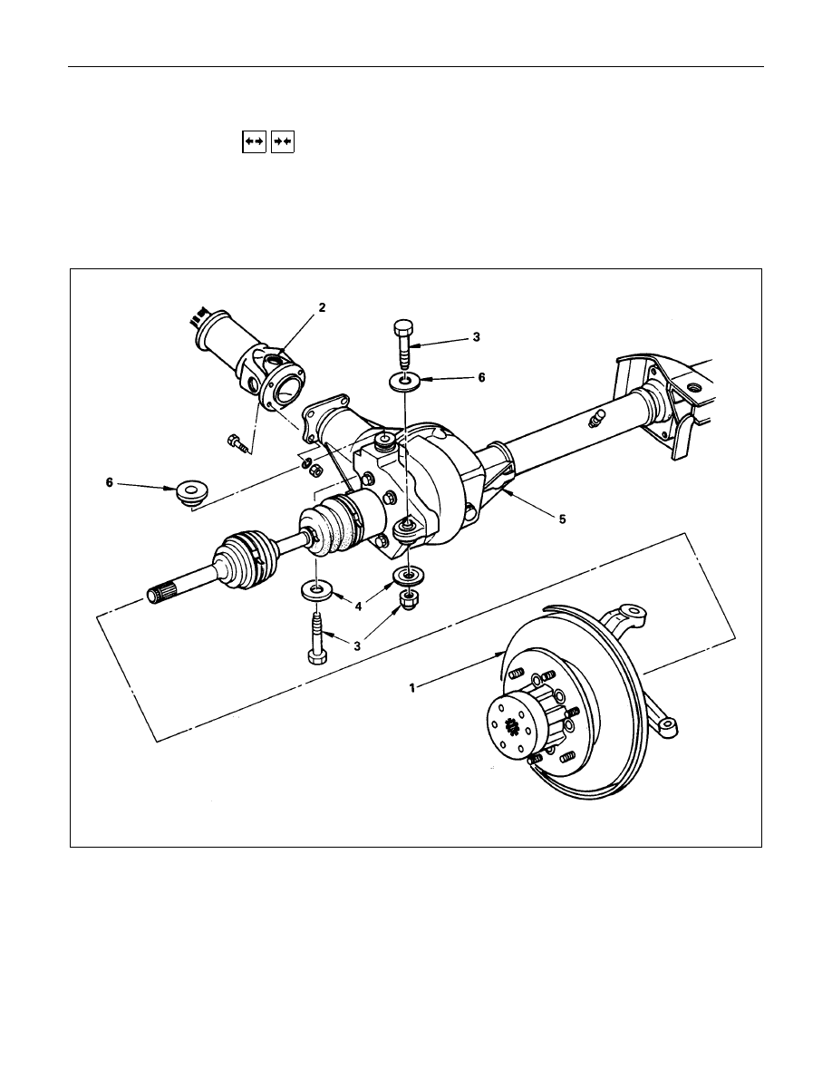
Removal Steps
▲
1. Assembly of hub and disc, back plate,
knuckle, knuckle arm, and lower end.
▲
2. Propeller shaft
3. Nut and bolt
4. Washer
▲
5. Front drive axle assembly
6. Washer
Installation Steps
6. Washer
▲
5. Front drive axle assembly
4. Washer
▲
3. Nut and bolt
▲
2. Propeller shaft
1. Assembly of hub and disc, back plate,
knuckle, knuckle arm, and lower end.
FRONT WHEEL DRIVE 4C1-13
Important Operations - Removal
1. Assembly of hub and disc, back plate, knuckle, knuckle
arm, and lower end.
Before removal, jack up the front of vehicle and support the
frame with jack stands.
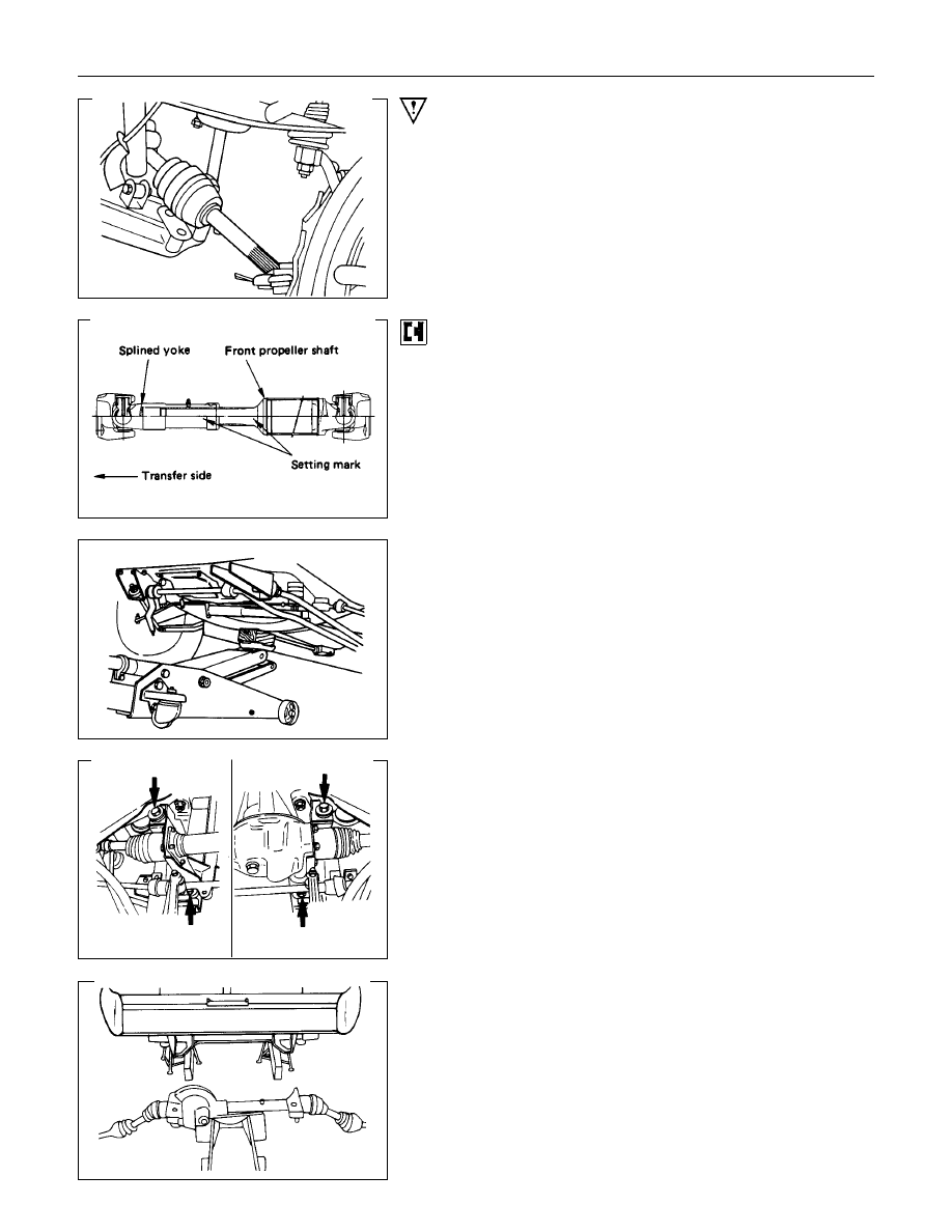
2. Propeller Shaft
Apply the setting marks.
5. Front Drive Axle Assembly
(1) Put the lifting jack under the center part of the front.
(2) Remove four bolts fixing axle case mounting brackets to the
frame.
Note :
Be careful not to damage birfield joints or double off-set
joints when supporting axle shaft assembly.
(3) Lower the front axle assembly and roll it out toward the front
of the vehicle.
Take care not to damage the birfield joints or the double off-
set joints.
Нет комментариевНе стесняйтесь поделиться с нами вашим ценным мнением.
Текст