Isuzu D-Max / Isuzu Rodeo (TFR/TFS). Manual — part 2057
3C-32 FRONT SUSPENSION
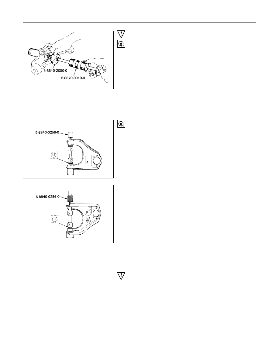
Important Operations
7. Needle Bearing (4
××××
4 model)
Remover : 5-8840-2000-0
(J-5822)
Sliding hammer : 5-8840-0019-0
(J-23907)
11.Camber Shims
12.Caster Shims
Note the positions and number of shims.
16.Bushing
Remover and installer : 5-8840-0256-0
(J-29755)
23.Lower Link Assembly
Before removal, remove the torsion bar, stabilizer bar and
shock absorber.
Brake hoses should be removed before disassembly and
installed after reassembly to avoid serious damage.

FRONT SUSPENSION 3C-33
25.Bushing : Rear Side
Remover and Installer : 5-8840-2124-0
(J-36834)
26.Bushing : Front Side
Remover and Installer : 5-8840-2123-0
(J-36833)
3C-34 FRONT SUSPENSION
INSPECTION AND REPAIR
Make necessary correction or parts replacement if wear, damage or any other abnormal conditions are found
through inspection.
•
Knuckle, Knuckle arm
•
Needle bearing, oil seal
(4
×
4 model)
•
Upper link, lower link, bushing
•
Upper end, lower end, boot
•
Fulcrum pin
•
Thrust washer
Visual Check
Inspect the following parts for wear, damage or other abnormal
conditions.
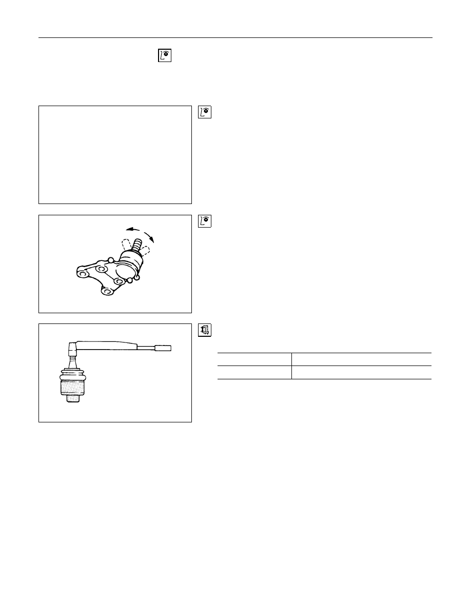
Upper Link End and Lower Link End
Inspect the upper and lower link end boot for damage or
grease leak.
Move the Ball Joint as shown in the illustration, then confirm its
normal movement.
Inspect screw/taper area of Ball Joint for defects.
If any defects are found by the above inspections, replace the
end assembly with new one.
After moving the Ball Joint 4 or 5 times, attach nuts then
measure the preload.
Preload
N
⋅
m (kgf
⋅
m/lb
⋅
ft)
Upper link end
0.9 - 3.2 (0.1 - 0.33/0.7 - 2.4)
Lower link end
0.06 - 0.64 (0.07 - 0.65/0.15 - 1.43)
If above limits specified are exceeded, replace the end
assembly.
FRONT SUSPENSION 3C-35
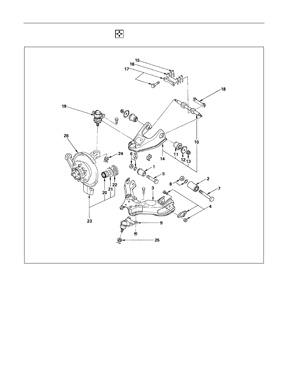
REASSEMBLY
Reassembly Steps
Lower Link
V
1. Bushing ; front
V
2. Bushing ; rear
3. Lower link assembly
V
4. Torsion bar arm
5. Bolt
V
6. Nut and washer
7. Bolt
V
8. Nut and washer
V
9. Lower End
Upper Link
10. Fulcrum pin
V
11. Bushing
12. Plate
V
13. Nut
V
14. Upper link assembly
V
15. Caster shims
V
16. Caster shims
V
17. Bolt and plate
18. Nut assembly
V
19. Upper end
Knuckle
V
20. Needle bearing (4
×
4 model)
21. Washer (4
×
4 model)
V
22. Oil seal (4
×
4 model)
23. Knuckle
V
24. Nut and cotter pin
V
25. Nut and cotter pin
26. Back plate
Нет комментариевНе стесняйтесь поделиться с нами вашим ценным мнением.
Текст