Isuzu D-Max / Isuzu Rodeo (TFR/TFS). Manual — part 2056
3C-28 FRONT SUSPENSION
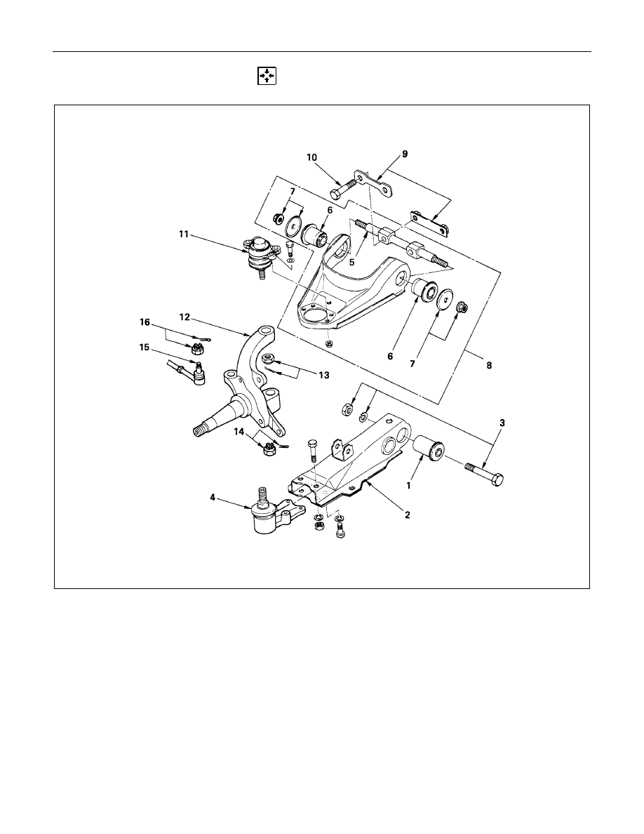
REASSEMBLY
Reassembly Steps
Lower Link
V
1. Bushing
2. Lower link assembly
V
3. Bolt, nut, and washer
V
4. Lower end
Upper Link
V
5. Fulcrum pin
V
6. Bushing
V
7. Plate and nut
8. Upper link assembly
9. Nut Assembly
V
10. Bolt and washer
V
11. Upper end
Knuckle
12. Knuckle
V
13. Nut and cotter pin
V
14. Nut and cotter pin
15. Steering link end
V
16. Nut and cotter pin
FRONT SUSPENSION 3C-29
Important Operations
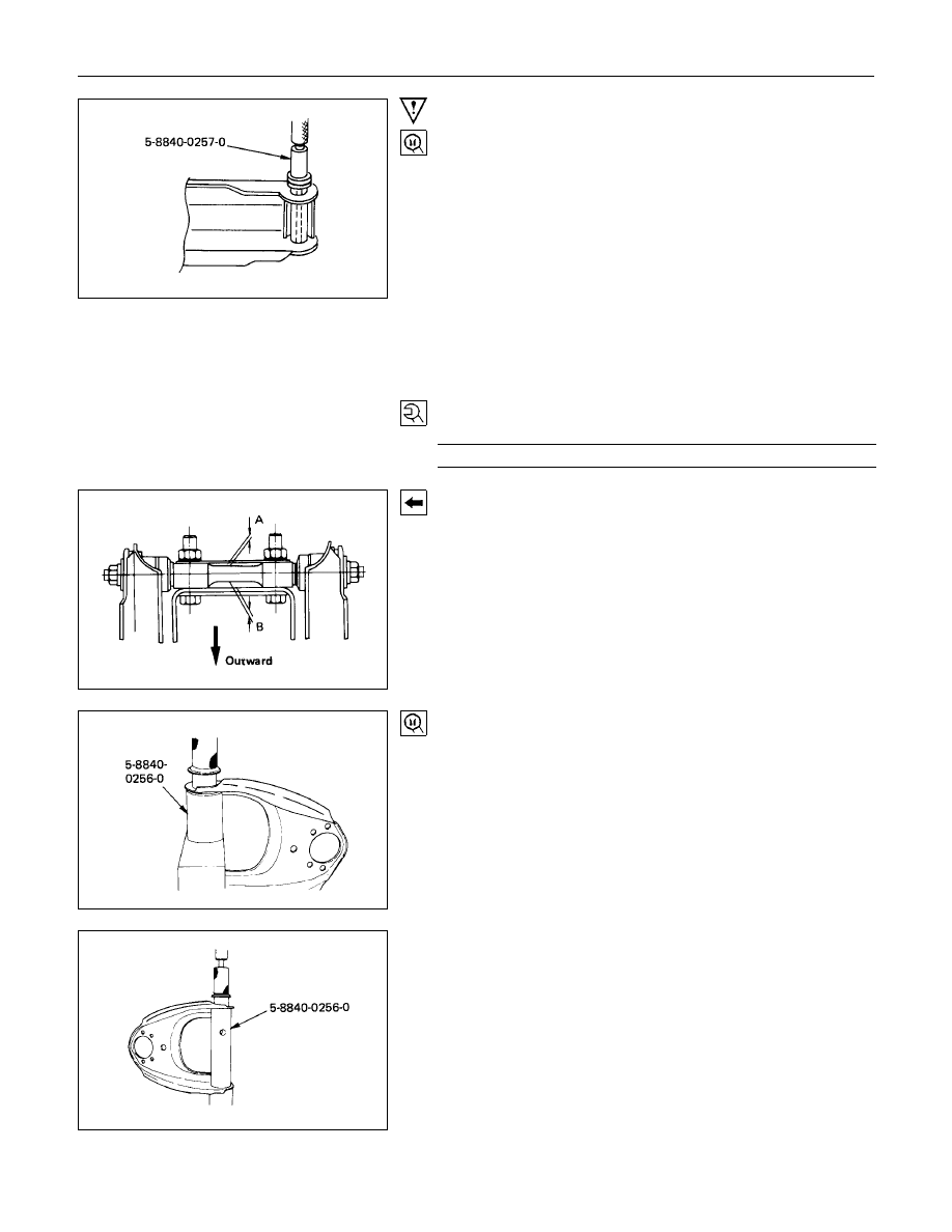
1. Bushing
Remover and Installer : 5-8840-0257-0
(J-29756)
3. Bolt, Nut and Washer
Tighten lower link nut finger-tight.
Perform the secure tightening after adjusting buffer clearance.
4. Lower End
Lower End Bolt Torque
N
⋅
m (kgf
⋅
m/lb
⋅
ft)
68.7
±
6.9 (7.0
±
0.7/50.6
±
5.1)
5. Fulcrum Pin
Install the smaller clearance A to be inside and larger
clearance B outside of vehicle.
6 Bushing
Remover and Installer : 5-8840-0256-0
(J-29755)
3C-30 FRONT SUSPENSION
7. Plate and Nut
Tighten fulcrum pin nut finger-tight.
Perform the secure tightening after adjusting buffer clearance.
10.Bolt
Fulcrum Pin Bolt Torque
N
⋅
m (kgf
⋅
m/lb
⋅
ft)
152.0
±
14.7 (15.5
±
1.5/112.1
±
10.8)
11.Upper End
Upper End Torque
N
⋅
m (kgf
⋅
m/lb
⋅
ft)
32.4
±
2.9 (3.3
±
0.3/23.9
±
2.2)
13.14. 16. Nut
Knuckle Nut Torque
N
⋅
m (kgf
⋅
m/lb
⋅
ft)
Lower End
147.1
±
9.8 (15.0
±
1.0/108.5
±
7.2)
Upper End
107.9
±
9.8 (10.0
±
1.0/79.7
±
7.2)
Steering Link End
107.9
±
9.8 (10.0
±
1.0/79.7
±
7.2)
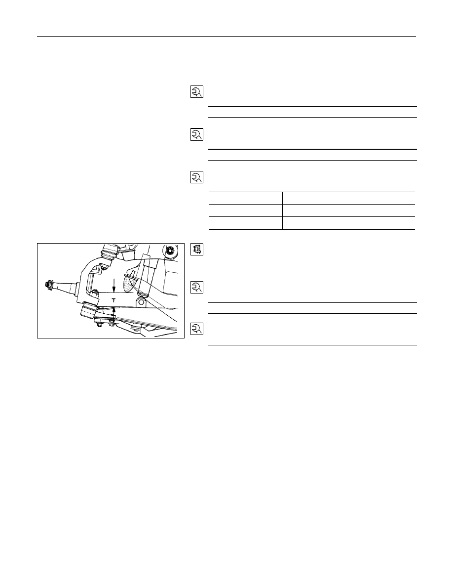
Fasten the bushing nut, and keep the buffer clearance as
shown on the left diagram.
T = 53 mm (2.09 in)
Lower Link Nut
Lower Link Nut Torque
N
⋅
m (kgf
⋅
m/lb
⋅
ft)
126.5
±
12.8 (12.9
±
1.3/93.3
±
9.4)
Upper Link Nut
Upper Link Nut Torque
N
⋅
m (kgf
⋅
m/lb
⋅
ft)
107.9
±
14.7 (11.0
±
1.5/79.6
±
10.8)
FRONT SUSPENSION 3C-31
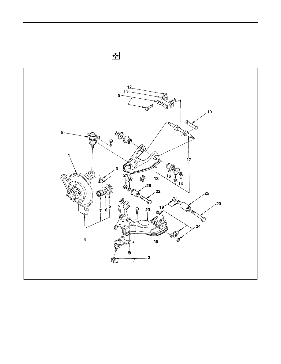
KNUCKLE, UPPER LINK AND LOWER LINK
(4
××××
4 AND 4
××××
2 SPORTY MODEL)
DISASSEMBLY
Disassembly Steps
Knuckle
1. Back plate and hub
2. Nut and cotter pin
3. Nut and cotter pin
4. Knuckle
5. Oil Seal (4
×
4 model)
6. Washer (4
×
4 model)
V
7. Needle bearing (4
×
4 model)
Upper Link
8. Upper end
9. Bolt and plate
10. Nut Assembly
V
11. Camber shims
V
12. Caster shims
13. Upper link assembly
14. Nut
15. Plate
V
16. Bushing
17. Fulcrum pin
Lower Link
18. Lower end
19. Nut and washer
20. Bolt
21. Nut and washer
22. Bolt
V
23. Lower link assembly
24. Torsion bar arm
V
25. Bushing
V
26. Bushing
Нет комментариевНе стесняйтесь поделиться с нами вашим ценным мнением.
Текст