Isuzu D-Max / Isuzu Rodeo (TFR/TFS). Manual — part 123

6E–96
4JH1 ENGINE DRIVEABILITY AND EMISSIONS
Condition for setting the DTC and action taken when the DTC sets
Circuit Description
The mass air flow (MAF) sensor is part of the intake air
system. It is fitted between the air cleaner and
turbocharger and measure the mass air flowing into the
engine.
The mass air flow (MAF) sensor element measures the
partial air mass through a measurement duct on the
sensor housing.
The ECM monitors the MAF sensor supply voltage and
MAF sensor output voltage. The supply voltage is out of
range, DTC P0100 (Symptom Code 7) or P0100
(Symptom Code 9) will be stored. The output voltage
excessively high or low, DTC P0100 (Symptom Code B)
or P0100 (Symptom Code C) will be stored.
Diagnostic Aids
An intermittent may be caused by the following:
• Poor connections.
• Misrouted harness.
• Rubbed through wire insulation.
• Broken wire inside the insulation.
Check for the following conditions:
• Poor connection at ECM-Inspect harness connectors
for backed out terminals, improper mating, broken
locks, improperly formed or damaged terminals, and
poor terminal to wire connection.
• Damaged harness-Inspect the wiring harness for
damage. If the harness appears to be OK, observe
the “Mass Air Flow” display on the Tech2 while
moving connectors and wiring harness related to the
sensor.
Diagnostic Trouble Code (DTC) P0100 (Symptom Code 7) (Flash Code 65)
Mass Air Flow (MAF) Sensor Voltage Supply Circuit High Input
Flash
Code
Code
Symptom
Code
MIL
DTC Name
DTC Setting Condition
Fail-Safe (Back Up)
65
P0100
7
ON
Mass Air Flow (MAF) Sensor
Voltage Supply Circuit High
Input
MAF sensor power supply
voltage is more than 5.2V.
ECM uses mass air flow
1600mg/strk & EGR 10% con-
ditions as substitute.
9
ON
Mass Air Flow (MAF) Sensor
Voltage Supply Circuit Low
Input
MAF sensor power supply
voltage is below 4.6V.
B
ON
Mass Air Flow (MAF) Sensor
Output Circuit Low Input
1. Engine speed is between
600rpm and 5000rpm.
2. MAF sensor output is below
-33.7mg/strk.
C
ON
Mass Air Flow (MAF) Sensor
Output Circuit High Input
1. Engine speed is between
600rpm and 5000rpm.
2. MAF sensor output is more
than 1784mg/strk.
Step
Action
Value(s)
Yes
No
1
Was the “On-Board Diagnostic (OBD) System Check”
performed?
—
Go to Step 2
Go to On Board
Diagnostic
(OBD) System
Check
2
1. Connect the Tech 2.
2. Review and record the failure information.
3. Select “F0: Read DTC Infor As Stored By ECU” in
“F0: Diagnostic Trouble Codes”.
Is the DTC P0100 (Symptom Code 7) stored as
“Present Failure”?
—
Go to Step 3
Refer to
Diagnostic Aids
and Go to Step
3
4JH1 ENGINE DRIVEABILITY AND EMISSIONS
6E–97
3
1. Using the Tech 2, ignition “On” and engine “Off”.
2. Select “F1: Clear DTC Information” in “F0:
Diagnostic Trouble Codes” with the Tech 2 and
clear the DTC information.
3. Operate the vehicle and monitor the “F0: Read
DTC Infor As Stored By ECU” in the “F0:
Diagnostic Trouble Codes”.
Was the DTC P0100 (Symptom Code 7) stored in this
ignition cycle?
—
Go to Step 4
Refer to
Diagnostic Aids
and Go to Step
4
4
Check for poor/faulty connection at the MAF sensor or
ECM connector. If a poor/faulty connection is found,
repair as necessary.
Was the problem found?
—
Verify repair
Go to Step 5
5
Visually check the MAF sensor.
Was the problem found?
—
Go to Step 11
Go to Step 6
6
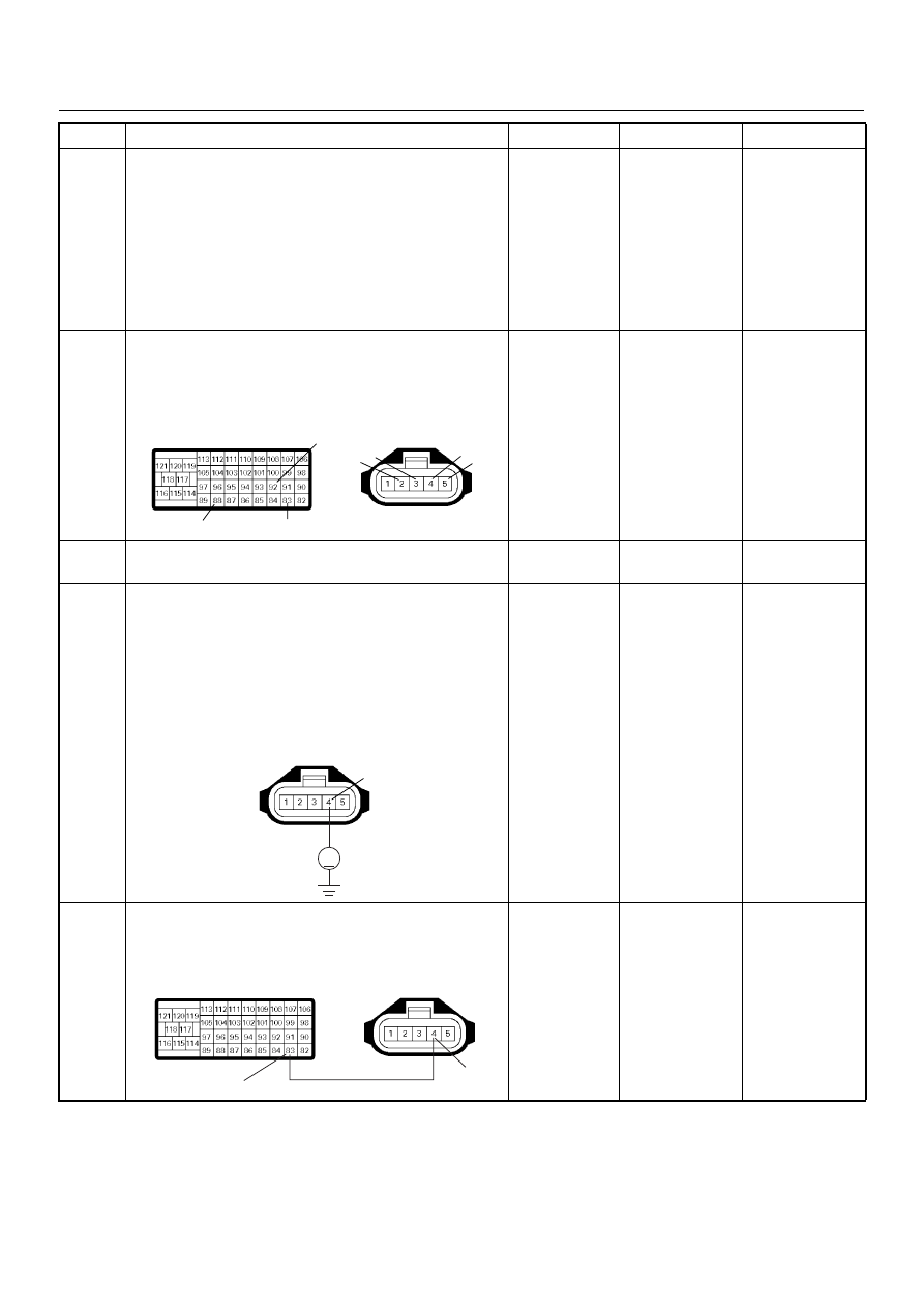
Using the DVM and check the MAF sensor power
supply circuit.
1. Ignition “On”, engine “Off”.
2. Disconnect the MAF & IAT sensor connector.
3. Check the circuit for short to battery voltage
circuit.
Was the DVM indicated specified value?
Approximately
5.0V
Go to Step 11
Less than 1V:
Go to Step 7
More than
specified value:
Go to Step 8
7
Repair the open circuit between the ECM and MAF
sensor.
Was the problem solved?
—
Verify repair
Go to Step 8
Step
Action
Value(s)
Yes
No
92
88
83
2 3
4
5
C-116
C-57(B)
V
4
C-116
83
4
C-116
C-57(B)
6E–98
4JH1 ENGINE DRIVEABILITY AND EMISSIONS
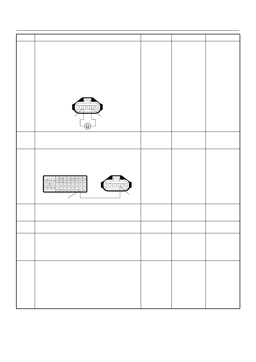
8
Using the DVM and check the MAF sensor power
supply circuit.
1. Ignition “Off”, engine “Off”.
2. Disconnect the MAF & IAT sensor connector and
ECM connector.
3. Check the circuit for short to MAF sensor heater
circuit.
Was the DVM indicated specified value?
No continuity
Go to Step 10
Go to Step 9
9
Repair the circuit for short to MAF sensor heater
circuit.
Is the action complete?
—
Verify repair
—
10
Repair the short to battery voltage circuit between the
ECM and MAF sensor.
Was the problem solved?
—
Verify repair
Go to Step 13
11
Substitute a known good MAF & IAT sensor assembly
and recheck.
Was the problem solved?
—
Go to Step 12
Go to Step 13
12
Replace the MAF & IAT sensor assembly.
Is the action complete?
—
Verify repair
—
13
Is the ECM programmed with the latest software
release?
If not, download the latest software to the ECM using
the “SPS (Service Programming System)”.
Was the problem solved?
—
Verify repair
Go to Step 14
14
Replace the ECM.
Is the action complete?
IMPORTANT: The replacement ECM must be
programmed. Refer to section of the Service
Programming System (SPS) in this manual.
Following ECM programming, the immobiliser system
(if equipped) must be linked to the ECM. Refer to
section 11 “Immobiliser System-ECM replacement” for
the ECM/Immobiliser linking procedure.
—
Verify repair
—
Step
Action
Value(s)
Yes
No
4
2
C-116
83
4
C-116
C-57(B)
4JH1 ENGINE DRIVEABILITY AND EMISSIONS
6E–99
Diagnostic Trouble Code (DTC) P0100 (Symptom Code 9) (Flash Code 65)
Mass Air Flow (MAF) Sensor Voltage Supply Circuit Low Input
Step
Action
Value(s)
Yes
No
1
Was the “On-Board Diagnostic (OBD) System Check”
performed?
—
Go to Step 2
Go to On Board
Diagnostic
(OBD) System
Check
2
1. Connect the Tech 2.
2. Review and record the failure information.
3. Select “F0: Read DTC Infor As Stored By ECU” in
“F0: Diagnostic Trouble Codes”.
Is the DTC P0100 (Symptom Code 9) stored as
“Present Failure”?
—
Go to Step 3
Refer to
Diagnostic Aids
and Go to Step
3
3
1. Using the Tech 2, ignition “On” and engine “Off”.
2. Select “F1: Clear DTC Information” in “F0:
Diagnostic Trouble Codes” with the Tech 2 and
clear the DTC information.
3. Operate the vehicle and monitor the “F0: Read
DTC Infor As Stored By ECU” in the “F0:
Diagnostic Trouble Codes”.
Was the DTC P0100 (Symptom Code 9) stored in this
ignition cycle?
—
Go to Step 4
Refer to
Diagnostic Aids
and Go to Step
4
4
Check for poor/faulty connection at the MAF sensor or
ECM connector. If a poor/faulty connection is found,
repair as necessary.
Was the problem found?
—
Verify repair
Go to Step 5
5
Visually check the MAF sensor.
Was the problem found?
—
Go to Step 10
Go to Step 6
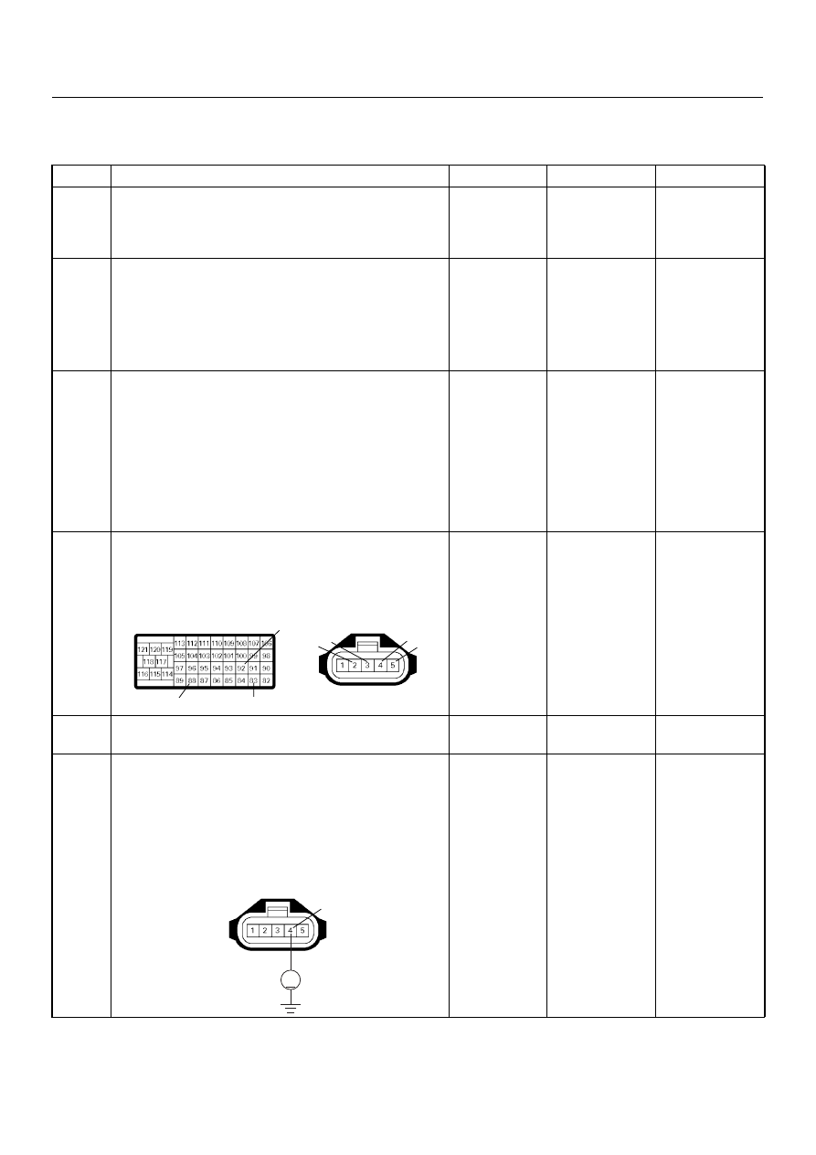
6
Using the DVM and check the MAF sensor power
supply circuit.
1. Ignition “On”, engine “Off”.
2. Disconnect the MAF & IAT sensor connector.
3. Check the circuit for short to ground circuit.
Was the DVM indicated specified value?
Approximately
5.0V
Go to Step 10
Go to Step 7
92
88
83
2 3
4
5
C-116
C-57(B)
V
4
C-116
Нет комментариевНе стесняйтесь поделиться с нами вашим ценным мнением.
Текст