Isuzu D-Max / Isuzu Rodeo (TFR/TFS). Manual — part 94
4JA1-TC/4JH1-TC ENGINE DRIVEABILITY AND EMISSIONS
6E–371
20
Substitute a known good MAF & IAT sensor assembly
and recheck.
Was the problem solved?
—
Go to Step 21
Go to Step 31
21
Replace the MAF & IAT sensor assembly.
Is the action complete?
—
Verify repair
—
22
1. Using the Tech 2, ignition “On” and engine “Off”.
2. Monitor the “Pedal/Throttle Position” and “Idle
Switch” in the data display.
Does the Tech 2 indicate correct “Pedal/Throttle
Position” from 0% to 100% and correct “Idle Switch”
status depending on accelerator pedal operation?
—
Go to Step 27
Go to Step 23
23
1. Using the Tech 2, ignition “On” and engine “Off”.
2. Monitor the “Pedal/Throttle Position” and “Idle
Switch” in the data display.
3. Adjust the accelerator cable or TPS within 0% to
100%.
Was the problem solved?
—
Verify repair
Go to Step 24
24
Check the TPS harness for the following conditions.
• Check for poor connector connection.
• Check for misrouted harness.
• Check for any accessory parts which may cause
electric interference.
If a problem is found, repair as necessary.
Was a problem found?
—
Verify repair
Go to Step 25
25
Substitute a known good TPS and recheck.
Was the problem solved?
—
Go to Step 26
Go to Step 31
26
Replace the TPS.
Is the action complete?
—
Verify repair
—
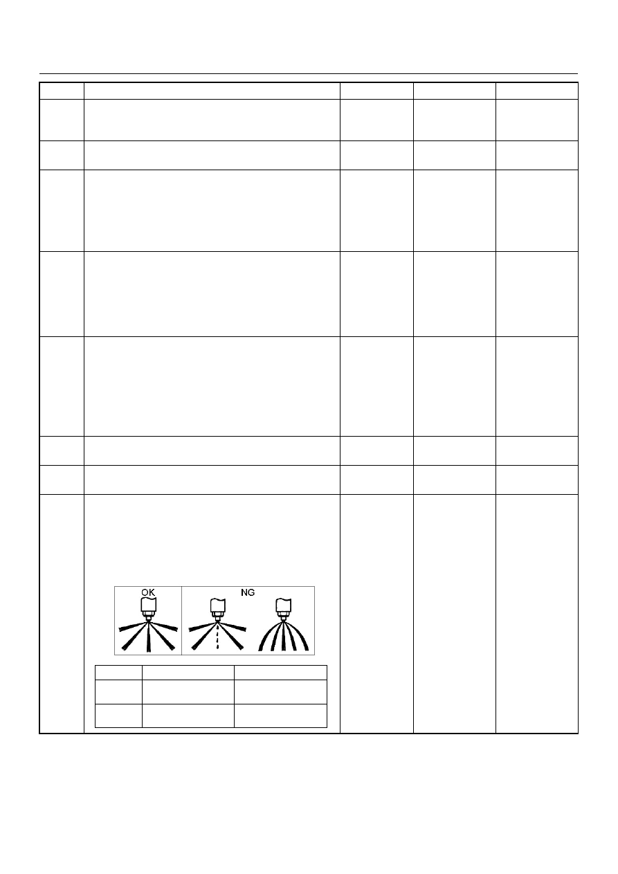
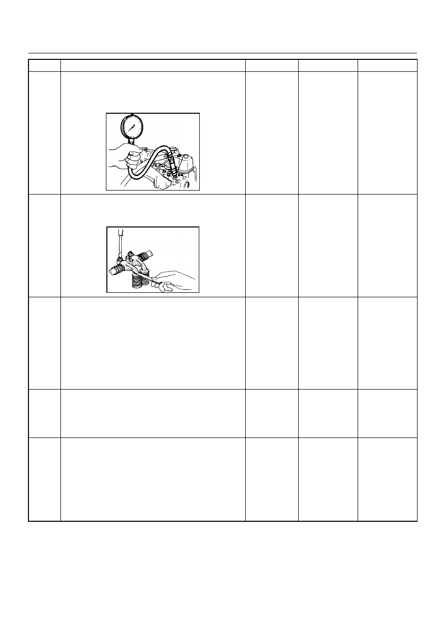
27
Remove the injection nozzles from the engine and
check for the following conditions.
• Improper splay condition.
• Operating pressure is incorrect.
If a problem is found, repair as necessary.
Was the problem found?
—
Replace the
injection nozzle
and verify repair
Go to Step 28
Step
Action
Value(s)
Yes
No
1
st
Stage
2
nd
Stage
4JA1-TC
19.5 - 20.5 Mpa
(199 -209 kg/cm
2
)
34.0 - 35.5 Mpa
(347 - 362 kg/cm
2
)
4JH1-TC
20.0 - 21.0 Mpa
(204 -214 kg/cm
2
)
34.3 - 35.8 Mpa
(350 - 365 kg/cm
2
)
6E–372
4JA1-TC/4JH1-TC ENGINE DRIVEABILITY AND EMISSIONS
28
Check the engine compression pressure for each
cylinders.
If a problem is found, repair as necessary.
Was the problem found?
More than 30
Mpa (31.0 kg/
cm
2
)
Verify repair
Go to Step 29
29
Check the inlet/exhaust valve clearance for each
valves.
Are the valve clearances within the specified value?
0.4mm at cold
(In/Ex)
Go to Step 30
Adjust and
verify repair
30
1. Review all diagnostic procedures within this table.
2. If all procedures have been completed and no
malfunctions have been found, review/inspect the
following:
• Visual/physical inspection
• Tech 2 data
• All electrical connections within a suspected circuit
and/or system
Was a problem found?
—
Verify repair
Go to Step 31
31
Is the ECM programmed with the latest software
release?
If not, download the latest software to the ECM using
the “SPS (Service Programming System)”.
Was the problem solved?
—
Verify repair
Go to Step 32
32
Substitute a known good ECM and recheck.
Was the problem solved?
IMPORTANT: The replacement ECM must be
programmed. Refer to section of the Service
Programming System (SPS) in this manual.
Following ECM programming, the immobiliser system
(if equipped) must be linked to the ECM. Refer to
section 11 “Immobiliser System-ECM replacement” for
the ECM/Immobiliser linking procedure.
—
Go to Step 33
Go to Step 34
Step
Action
Value(s)
Yes
No

4JA1-TC/4JH1-TC ENGINE DRIVEABILITY AND EMISSIONS
6E–373
33
Replace the ECM.
Is the action complete?
IMPORTANT: The replacement ECM must be
programmed. Refer to section of the Service
Programming System (SPS) in this manual.
Following ECM programming, the immobiliser system
(if equipped) must be linked to the ECM. Refer to
section 11 “Immobiliser System-ECM replacement” for
the ECM/Immobiliser linking procedure.
—
Verify repair
—
34
Replace the injection pump assembly.
Is the action complete?
—
Verify repair
—
Step
Action
Value(s)
Yes
No

6E–374
4JA1-TC/4JH1-TC ENGINE DRIVEABILITY AND EMISSIONS
EXCESSIVE WHITE SMOKE
Step
Action
Value(s)
Yes
No
1
Was the “On-Board Diagnostic (OBD) System Check”
performed?
—
Go to Step 2
Go to On Board
Diagnostic
(OBD) System
Check
2
1. Perform a bulletin search.
2. If a bulletin that addresses the symptom is found,
correct the condition as instructed in the bulletin.
Was a bulletin found that addresses the symptom?
—
Verify repair
Go to Step 3
3
Was a visually/physical check performed?
—
Go to Step 4
Go to Visual /
physical Check.
4
Is the customer using the incorrect fuel type?
Diesel fuel
only
Replace with
diesel fuel
Go to Step 5
5
Check the engine coolant consumption to verify that it
leaks to combustion chamber or exhaust through the
gasket.
Was a problem found?
—
Verify repair
Go to Step 6
6
Check the ECM & PSG grounds to verify that they are
clean and tight. Refer to the ECM wiring diagrams.
Was a problem found?
—
Verify repair
Go to Step 7
7
1. Using the Tech 2, display the ECT sensor and IAT
sensor value.
2. Check the displayed value.
Does the Tech 2 indicate correct temperature
depending on engine condition?
If a problem is found, repair as necessary.
Was the problem found?
—
Verify repair
Go to Step 8
8
1. Using the Tech 2, display the FT sensor value.
2. Check the displayed value.
Does the Tech 2 indicate correct temperature
depending on engine condition?
If a problem is found, repair as necessary.
Was the problem found?
—
Go to Step 30
Go to Step 9
9
1. Using the Tech 2, ignition “On” and engine “Run”.
2. Monitor the “Mass Air Flow” in the data display.
Does the Tech 2 indicate correct “Mass Air Flow”
depending on accelerator pedal operation?
—
Go to Step 14
Go to Step 10
10
Remove the MAF & IAT sensor assembly and check
for the following conditions.
• Objects blocking at the MAF sensor element.
If a problem is found, repair as necessary.
Was the problem found?
—
Verify repair
Go to Step 11
11
Check the MAF sensor harness for the following
conditions.
• Check for poor connector connection.
• Check for misrouted harness.
• Check for any accessory parts which may cause
electric interference.
If a problem is found, repair as necessary.
Was a problem found?
—
Verify repair
Go to Step 12
Нет комментариевНе стесняйтесь поделиться с нами вашим ценным мнением.
Текст