Isuzu D-Max / Isuzu Rodeo (TFR/TFS). Manual — part 1414

ELECTRICAL-BODY AND CHASSIS 8-221
TROUBLE SHOOTING
Rear defogger inoperative
Checkpoint
Trouble Cause
Countermeasure
Reinstall or replace the fuse
No. CB-7 (15A) (RHD: fuse
No. CB-5 (15A))
Poor fuse contact or blown
NG
Reinstall or replace the fuse
No. CB-13 (15A)
Fuse No. CB-13 (15A, Fuse
box)
Poor fuse contact or blown
Replace the rear defogger
switch
Rear defogger switch function
Switch malfunction
NG
NG
OK
OK
OK
LHD:
Fuse No. CB-7 (15A, Fuse
box)
RHD:
Fuse No. CB-5 (15A, Fuse
box)
Replace the rear defogger
relay
Relay malfunction
NG
Continued on the next page
Rear defogger relay function
Repair grounding point
(
B-28
) contact
Grounding point (
B-28
)
Poor grounding point contact
NG
OK
Repair open circuit or poor
connector contact between
fuse No. CB-7 (15A) (RHD:
fuse No. CB-5 (15A)) and 2
B-7
, fuse No. CB-13 (15A)
and 5
B-7
, 1
B-7
and 1
L-4
, 4
B-7
and 4
B-15
or
5
B-15
and
B-28
Voltage between 1
L-4
-
ground when the starter switch
and the rear defogger switch
are at on position (should be
battery voltage present)
Open circuit or poor connector
contact
NG
OK

8-222 ELECTRICAL-BODY AND CHASSIS
Checkpoint
Trouble Cause
Countermeasure
OK
Repair open circuit or
connector contact between 1
L-7
and
B-28
Open circuit or poor connector
contact
NG
Continued from the previous page
Continuity between 1
L-7
and
B-28
Repair heat wire
Continuity between rear
defogger terminals
Broken heat wire of rear
defogger
NG
OK
ELECTRICAL-BODY AND CHASSIS 8-223
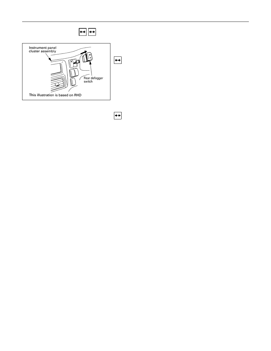
REMOVAL AND INSTALLATION
REAR DEFOGGER SWITCH (Except
South Africa, Chile)
Removal
1. Instrument Panel Cluster Assembly
• Refer to Section 10 “BODY” for instrument panel cluster
assembly removal steps.
2. Rear Defogger Switch
• Disconnect the switch connector.
• To remove the switch, push the lock from the back side
of the cluster assembly.
Installation
Follow the removal procedure in the reverse order to install the
rear defogger switch.

8-224 ELECTRICAL-BODY AND CHASSIS
INSPECTION AND REPAIR
Switch side
REAR DEFOGGER SWITCH
Rear Defogger Switch Connections
Terminal No.
SW position
3
5
4
6
2
ON
OFF
REAR DEFOGGER RELAY
Check continuity between the relay terminals.
1
-
5
. . . . . . No continuity
(When battery voltage is applied between
2
and
4
)
1
-
5
. . . . . . Continuity
INSPECTION OF REAR DEFOGGER HEAT
WIRE
• Heat wires are printed on the inner side of glass.
To clean, use a soft cloth and wipe horizontally along the
wires.
• Never use glass cleaner or equivalent.
• When measuring voltage, wind a piece of tin foil around the
tip of the negative probe and press the foil against the wire
with your finger as shown.
(1) Turn the ignition switch on.
(2) Turn the defogger switch on.
(3) Measure the voltage between the three points on the heat
wire and the (-) terminal with a voltmeter.
(4) Check that the voltage becomes smaller from
A
to
B
to
C
.
Нет комментариевНе стесняйтесь поделиться с нами вашим ценным мнением.
Текст