Isuzu D-Max / Isuzu Rodeo (TFR/TFS). Manual — part 158
6E–236
4JH1 ENGINE DRIVEABILITY AND EMISSIONS
Diagnostic Trouble Code (DTC) P1120 (Symptom Code 9) (Flash Code 21)
Pedal/Throttle Position Sensor Voltage Supply Circuit Low Input
Step
Action
Value(s)
Yes
No
1
Was the “On-Board Diagnostic (OBD) System Check”
performed?
—
Go to Step 2
Go to On Board
Diagnostic
(OBD) System
Check
2
1. Connect the Tech 2.
2. Review and record the failure information.
3. Select “F0: Read DTC Infor As Stored By ECU” in
“F0: Diagnostic Trouble Codes”.
Is the DTC P1120 (Symptom Code 9) stored as
“Present Failure”?
—
Go to Step 3
Refer to
Diagnostic Aids
and Go to Step
3
3
1. Using the Tech 2, ignition “On” and engine “Off”.
2. Select “F1: Clear DTC Information” in “F0:
Diagnostic Trouble Codes” with the Tech 2 and
clear the DTC information.
3. Operate the vehicle and monitor the “F0: Read
DTC Infor As Stored By ECU” in the “F0:
Diagnostic Trouble Codes”.
Was the DTC P1120 (Symptom Code 9) stored in this
ignition cycle?
—
Go to Step 4
Refer to
Diagnostic Aids
and Go to Step
4
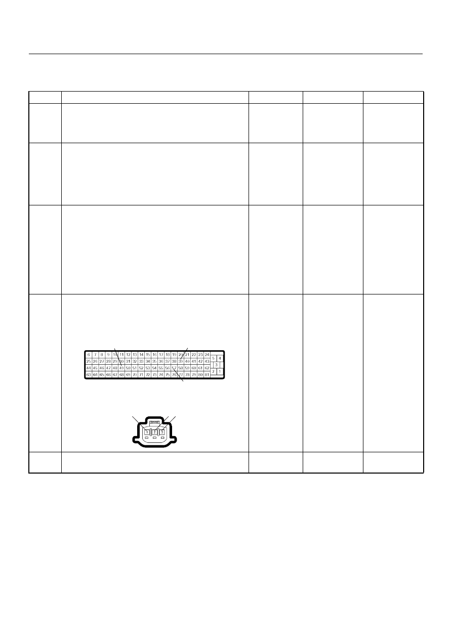
4
Check for poor/faulty connection at the TPS or ECM
connector. If a poor/faulty connection is found, repair
as necessary.
Was the problem found?
—
Verify repair
Go to Step 5
5
Visually check the TPS.
Was the problem found?
—
Go to Step 10
Go to Step 6
49
39
57
2 3
1
C-56
E-22
4JH1 ENGINE DRIVEABILITY AND EMISSIONS
6E–237
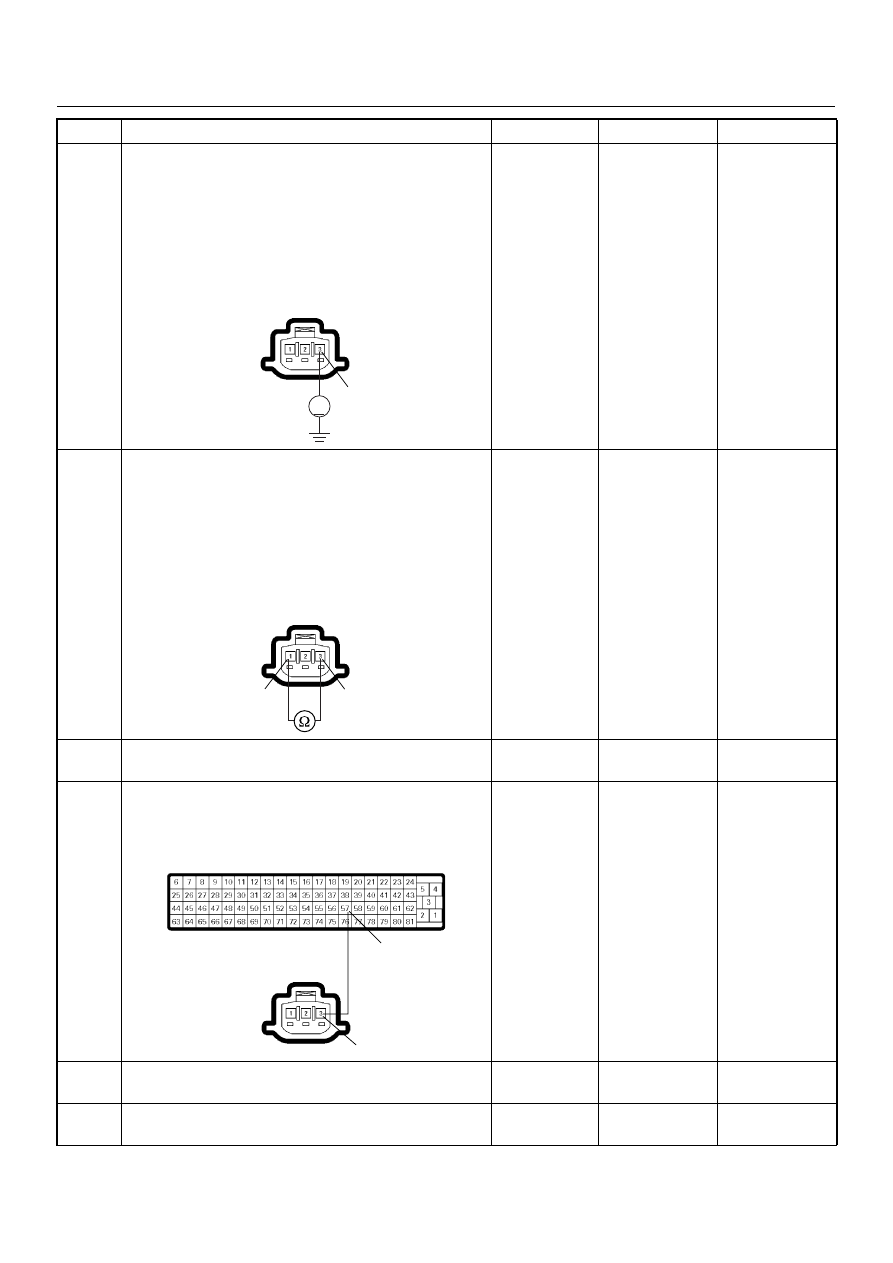
6
Using the DVM and check the TPS power supply
circuit.
1. Ignition “On”, engine “Off”.
2. Disconnect the TPS connector.
3. Check the circuit for short to battery voltage
circuit.
Was the DVM indicated specified value?
Approximately
5.0V
Go to Step 10
Go to Step 7
7
Using the DVM and check the TPS power supply
circuit.
1. Ignition “Off”, engine “Off”.
2. Disconnect the TPS connector and ECM
connector.
3. Check the circuit for short to TPS ground circuit.
Was the DVM indicated specified value?
No continuity
Go to Step 9
Go to Step 8
8
Repair the circuit for short to TPS ground circuit.
Is the action complete?
—
Verify repair
—
9
Repair the short to ground circuit between the ECM
and TPS.
Was the problem solved?
—
Verify repair
Go to Step 12
10
Substitute a known good TPS and recheck.
Was the problem solved?
—
Go to Step 11
Go to Step 12
11
Replace the TPS.
Is the action complete?
—
Verify repair
—
Step
Action
Value(s)
Yes
No
V
3
E-22
3
1
E-22
57
3
C-56
E-22

6E–238
4JH1 ENGINE DRIVEABILITY AND EMISSIONS
12
Is the ECM programmed with the latest software
release?
If not, download the latest software to the ECM using
the “SPS (Service Programming System)”.
Was the problem solved?
—
Verify repair
Go to Step 13
13
Replace the ECM. Is the action complete?
IMPORTANT: The replacement ECM must be
programmed. Refer to section of the Service
Programming System (SPS) in this manual.
Following ECM programming, the immobiliser system
(if equipped) must be linked to the ECM. Refer to
section 11 “Immobiliser System-ECM replacement” for
the ECM/Immobiliser linking procedure.
—
Verify repair
—
Step
Action
Value(s)
Yes
No

4JH1 ENGINE DRIVEABILITY AND EMISSIONS
6E–239
Diagnostic Trouble Code (DTC) P1120 (Symptom Code D) (Flash Code 21)
Pedal/Throttle Position Sensor Brake Switch Error
Step
Action
Value(s)
Yes
No
1
Was the “On-Board Diagnostic (OBD) System Check”
performed?
—
Go to Step 2
Go to On Board
Diagnostic
(OBD) System
Check
2
1. Connect the Tech 2.
2. Review and record the failure information.
3. Select “F0: Read DTC Infor As Stored By ECU” in
“F0: Diagnostic Trouble Codes”.
Is the DTC P1120 (Symptom Code D) stored as
“Present Failure”?
—
Go to Step 3
Refer to
Diagnostic Aids
and Go to Step
3
3
1. Using the Tech 2, ignition “On” and engine “Off”.
2. Select “F1: Clear DTC Information” in “F0:
Diagnostic Trouble Codes” with the Tech 2 and
clear the DTC information.
3. Operate the vehicle and monitor the “F0: Read
DTC Infor As Stored By ECU” in the “F0:
Diagnostic Trouble Codes”.
Was the DTC P1120 (Symptom Code D) stored in this
ignition cycle?
—
Go to Step 4
Refer to
Diagnostic Aids
and Go to Step
4
4
Visually check the TPS.
Check for the following conditions.
• Accelerator pedal sticking.
If a problem is found, repair as necessary.
Was the problem found?
—
Verify repair
Go to Step 5
5
1. Using the Tech 2, ignition “On” and engine “Off”.
2. Monitor the “Throttle Position” in the data display.
Does the Tech 2 indicate correct “Throttle Position”
from 0% to 100% depending on accelerator pedal
operation?
—
Go to Step 7
Go to Step 6
6
1. Using the Tech 2, ignition “On” and engine “Off”.
2. Monitor the “Throttle Position” in the data display.
3. Adjust the TPS within 0% to 100%.
Was the problem solved?
—
Verify repair
Go to Step 11
7
1. Using the Tech 2, ignition “On” and engine “Off”.
2. Monitor the “Brake Switch 1” and “Brake Switch 2”
in the data display.
Does the Tech 2 indicate “Inactive” when the brake
pedal was not stepped on?
—
Go to Step 13
Go to Step 8
8
Adjust the brake switch.
Was the problem solved?
—
Verify repair
Go to Step 9
9
Substitute a known good brake switch and recheck.
Was the problem solved?
—
Go to Step 10
Go to Step 13
10
Replace the brake switch.
Is the action complete?
—
Verify repair
—
11
Substitute a known good TPS and recheck.
Was the problem solved?
—
Go to Step 12
Go to Step 13
12
Replace the TPS.
Is the action complete?
—
Verify repair
—
Нет комментариевНе стесняйтесь поделиться с нами вашим ценным мнением.
Текст