Isuzu D-Max / Isuzu Rodeo (TFR/TFS). Manual — part 307

AUTOMATIC TRANSMISSION (AW30-40LE) 7A-77
DTC P1120 (FLASHING CODE 22)
PWM THROTTLE SIGNAL FAILURE (TH) (For TFR/S)
Step Action
Value(s)
Yes
No
1
1. Connect a analog voltmeter between the
TCM 28 pin connector terminal (6) and TCM
20 pin connector terminal (15 or 19).
2. Turn the ignition "ON".
Is the voltage within the specified value?
4.4-4.6 V
*
Go to Step 2
Go to Step 3
2
Open the throttle fully.
Is the voltage within the specified value?
0.4-0.6 V
*
The problem is
intermittent.
Refer to
"Diagnostic
aids".
Go to Step 3
3
1. Turn the ignition "ON".
2. Measure the voltage between the ECM 81
pin connector terminal (26) and ground
terminal (47) (TFR/S), or ECM 32 pin
connector terminal (14) and ground terminal
(33 or 49) ('01 TFR, for Thailand).
Is the voltage within the specified value?
4.4-4.6 V
*
Go to Step 4
Go to Step 6
4
Open the throttle fully.
Is the voltage within the specified value?
0.4-0.6 V
*
Go to Step 5
Go to Step 6
5
Check the wiring harness between the TCM 28
pin connector terminal (6) and ECM 81 pin
connector terminal (26) (TFR/S), or ECM 32 pin
connector terminal (14) ('01 TFR, for Thailand).
Or TCM is faulty.
Was a problem found and corrected?
Go to Step 9
6
1. Disconnect the TPS connector.
2. Connect a voltmeter between the TPS
connector terminal (C93-3) and (C93-1)
(TFR/S), or TPS connector terminal (B17-2)
and (B17-1), or (B18-3) and (B18-2) ('01
TFR, for Thailand).
Is the voltage within the specified value?
4.99-5.01 V
Go to Step 7
Go to Step 8
7
Check the TPS connectors. If OK, replace the
TPS.
Is the replacement complete?
Go to Step 9
8
Check the wiring harness between the TPS and
ECM.
If OK, replace the ECM.
Is the replacement complete?
Go to Step 9
7A-78 AUTOMATIC TRANSMISSION (AW30-40LE)
DTC P1120 (FLASHING CODE 22)
PWM THROTTLE SIGNAL FAILURE (TH) (For TFR/S) (Cont’d)
Step Action
Value(s)
Yes
No
9
1. After the repair is complete, use the scan tool
to select "DTC", then "Clear Info" function.
2. Make a road running test for the vehicle.
3. Review the scan tool "DTC Info".
Has the last test failed or is the current DTC
displayed?
Begin the
diagnosis
again.
Go to Step 1
System OK
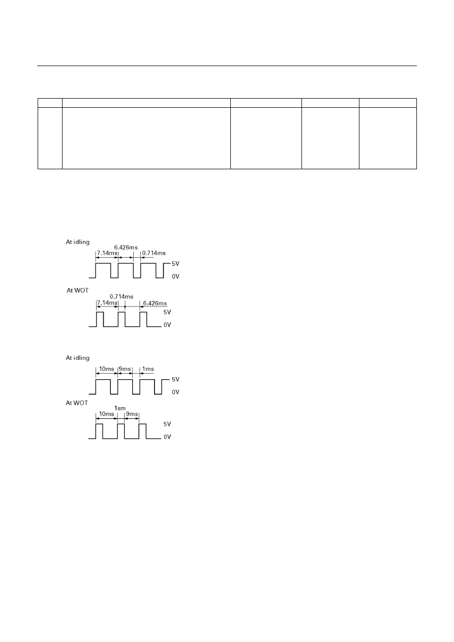
*Reference (Oscilloscope waveform)
(TFR/S)
('01 TFR, for Thailand)
AUTOMATIC TRANSMISSION (AW30-40LE) 7A-79
DTC P1121 (FLASHING CODE 23)
ANALOG THROTTLE SIGNAL FAILURE (VREF, VGND)(For UBS)
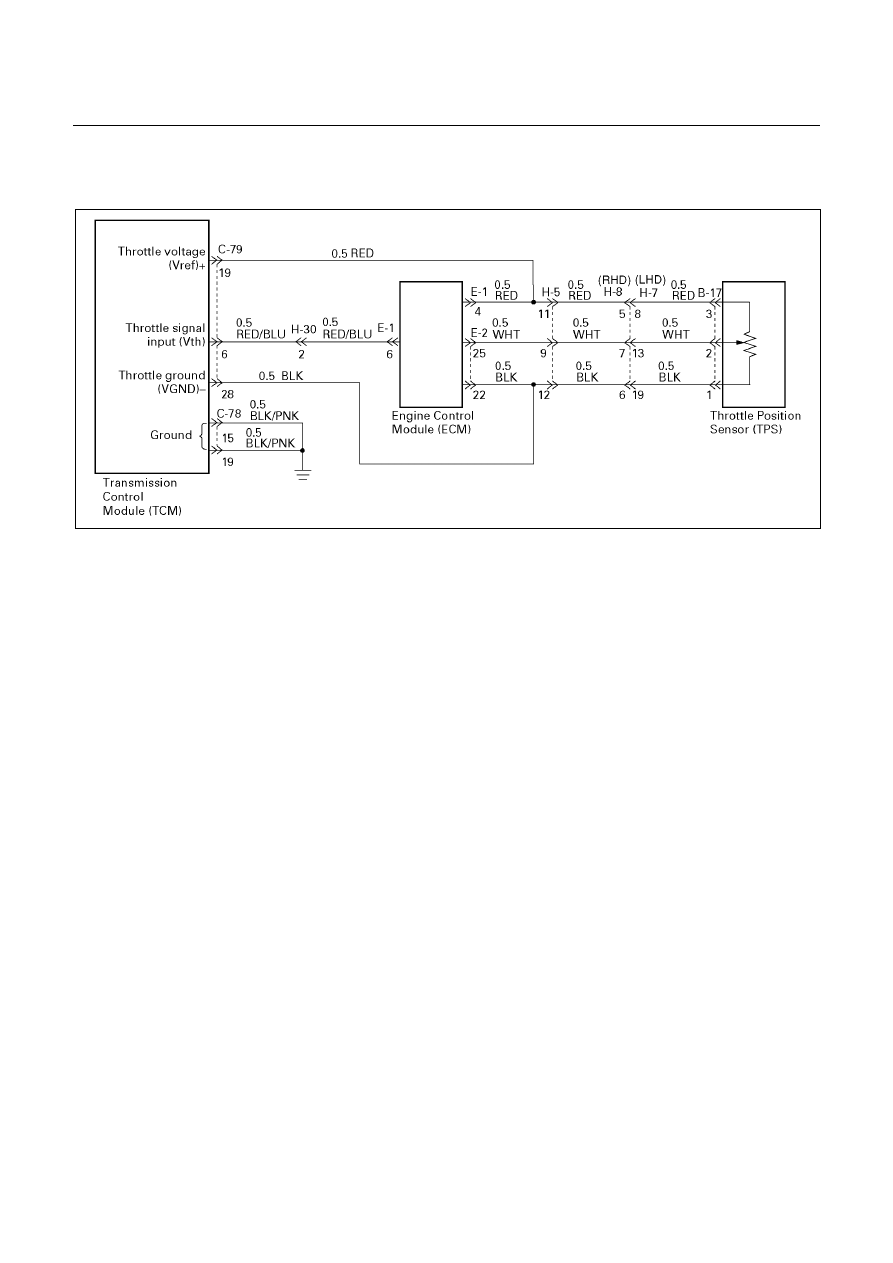
D07R200063
Circuit description:
When the signal of the engine throttle position sensor
located on the accelerator pedal is supplied to the
transmission TCM, the TCM judges the opening
condition of the throttle.
The shift point of the transmission is determined by this
opening condition of the throttle.
Fail-safe control:
The TCM controls fail-safe by detecting analog throttle
signal (VREF, VGND) failure.
Failure detection:
• When the Vref input voltage is detected more than
5.55V or less than 4.45V.
• When the Vgnd input voltage is detected more than
0.40V or less than -0.40V.
• When the failure criteria is continuously for 1.0 sec.
Contents of control:
At failure detection
• Judges throttle opening of linear sensor (Vth) as
Vref:5V, Vgnd:0V
• Throttle learning control inhibit
• Up hill and down hill control inhibit
At failure decision
Executes following items in addition to above
control items at failure detection.
• Stores the failure information in failure-memory
Conditions of turning “CHECK TRANS” lamp
off:
None
Reversion conditions from fail-safe:
At failure detection
When the Vref input voltage is detected less than 5.55
V and more than 4.45 V.
When the Vgnd input voltage is detected less than 0.40
V and more than -0.40 V.
At failure decision
• Recovers when judged 0km/h by output revolution
sensor after the Vref input voltage is detected less
than 5.55V and more than 4.45V.
(however, uses 0 km/h judgment by back-up
vehicle speed at output revolution failure)
• Recovers when judged 0km/h by output revolution
sensor after the Vgnd input voltage is detected less
than 0.40V and more than -0.40V.
(however, uses 0 km/h judgment by back-up
vehicle speed at output revolution failure)
Test description:
The following numbers correspond to the step numbers
on the diagnostic chart.
1. Check the power supply voltage (4.75-5.25V) of
throttle position sensor.
Diagnostic aids:
An intermittent may be caused by a poor connection,
rubbed through wire insulation or a wire broken inside
the insulation. Inspect related harness connector for
backed out terminals, improper mating, broken locks,
improperly formed or damaged terminals, poor terminal
to wire connection and damaged harness.

7A-80 AUTOMATIC TRANSMISSION (AW30-40LE)
DTC P1121 (FLASHING CODE 23)
ANALOG THROTTLE SIGNAL FAILURE (VREF, VGND)(For UBS)
Step Action
Value(s)
Yes
No
1
1. With the engine "OFF", turn the ignition
"ON".
2. Connect a voltmeter between the TCM 28
pin connector terminal (19) and (28).
Is the voltage within the specified value?
4.75-5.25 V
The problem is
intermittent.
Refer to
"Diagnostic
aids".
Go to Step 2
2
Connect a voltmeter between the ECM 32 pin
connector terminal (E1-4) and (E2-22).
Is the voltage within the specified value?
4.75-5.25 V
Go to Step 3
Go to Step 4
3
Check the wiring harness between the TCM and
ECM.
Was a problem found and corrected?
Go to Step 5
4
Check the ECM 32 pin connectors. If OK,
replace the ECM.
Is the replacement complete?
Go to Step 5
5
1. After the repair is complete, use the scan tool
to select "DTC", then "Clear Info" function.
2. Make a road running test for the vehicle.
3. Review the scan tool "DTC Info".
Has the last test failed or is the current DTC
displayed?
Begin in the
diagnosis
again. Go to
Step 1
System OK
Нет комментариевНе стесняйтесь поделиться с нами вашим ценным мнением.
Текст