Isuzu D-Max / Isuzu Rodeo (TFR/TFS). Manual — part 1662
1-34 HEATING AND AIR CONDITIONING
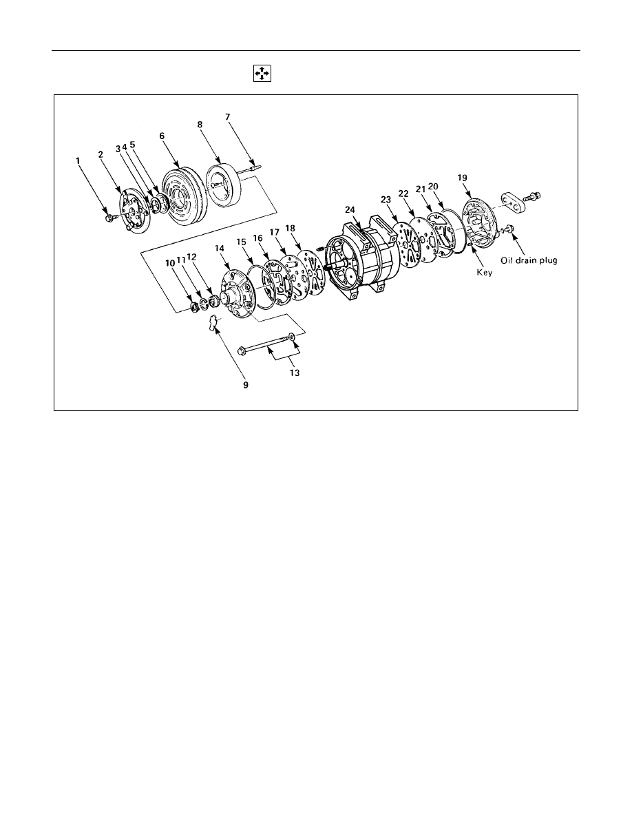
DISASSEMBLY
Disassembly Steps
▲
1. Drive plate bolt
▲
2. Drive plate
3. Shim(s)
4. Snap ring
▲
5. Cover (If so equipped)
▲
6. Pulley assembly
7. Lead wire connector
▲
8. Field coil
9. Felt (If so equipped)
▲
10. Shaft seal cover (If so equipped)
▲
11. Snap ring
▲
12. Shaft seal assembly
13. Through bolt with gasket
▲
14. Front cylinder head
▲
15. O-ring
16. Gasket
17. Front valve plate
▲
18. Front suction valve
▲
19. Rear cylinder head
▲
20. O-ring
21. Gasket
22. Rear valve plate
23. Rear suction valve
▲
24. Cylinder and shaft assembly
HEATING AND AIR CONDITIONING 1-35
Important Operations - Dissassembly
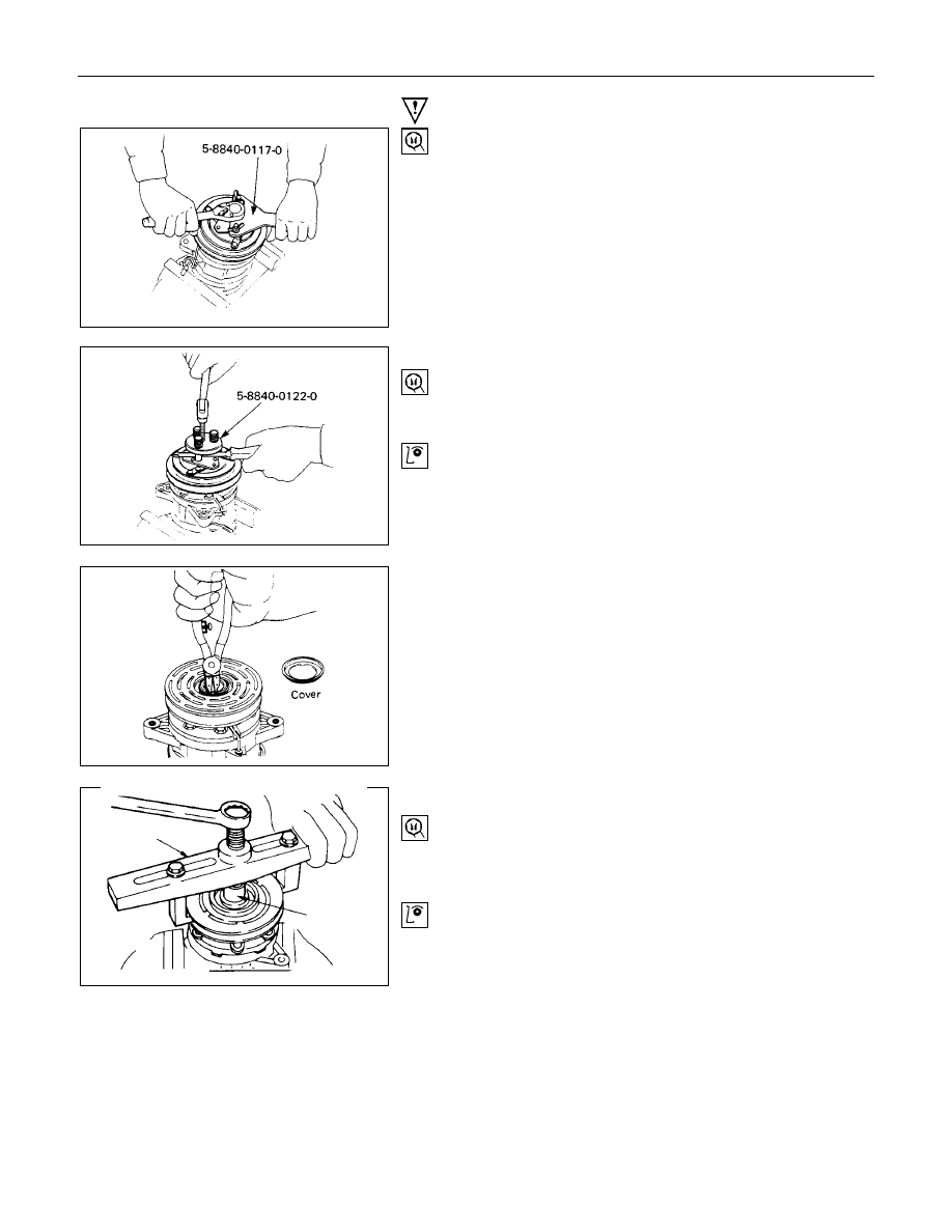
1. Drive Plate Bolt
Using drive plate holder to prevent the drive plate from
rotating, then remove the bolt.
Drive Plate Holder: 5-8840-0117-0 (J-33939)
2. Drive Plate
Using drive plate puller and forcing screw to remove the
drive plate.
Drive Plate Puller: 5-8840-0122-0 (J-33944-A)
If the frictional surface shows signs of damage due to
excessive heat, the drive plate and pulley should be
replaced.
5. Cover (If so equipped)
Using snap ring pliers to remove the snap ring.
5-8840-0111-0
5-8840-0121-0
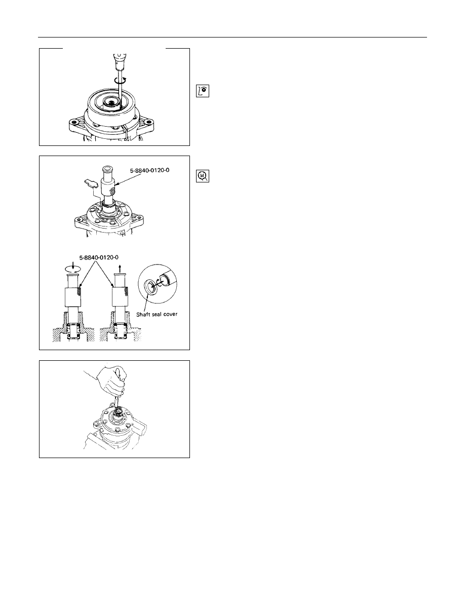
6. Pulley Assembly
Using pulley puller pilot and pulley puller to remove the
pulley assembly.
Pulley Puller Pilot: 5-8840-0121-0 (J-33943)
Pulley Puller:
5-8840-0111-0 (J-8433)
Check the appearance of the pulley assembly. If the
frictional surface of the pulley shows signs of excessive
grooving due to slippage, both the pulley and drive plate
should be replaced. The frictional surfaces of the pulley
assembly should be cleaned with a suitable solvent before
reinstallation.
1-36 HEATING AND AIR CONDITIONING
8.Field Coil
Loosen three screws and remove the field coil with lead
wire.
Check coil for loose connector or cracked insulation.
10.Shaft Seal Cover (If so equipped)
Using shaft seal remover to remove the shaft seal cover.
Engage the remover hook with the shaft seal cover groove
and slowly draw the shaft seal cover out.
Shaft Seal Remover: 5-8840-0120-0 (J-33942)
11.Snap Ring
Using snap ring pliers to remove the snap ring.
HEATING AND AIR CONDITIONING 1-37
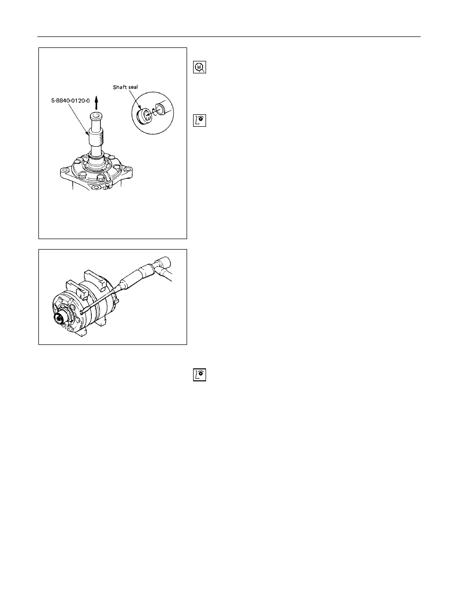
12.Shaft Seal Assembly
Using shaft seal remover to remove the shaft seal
assembly.
Engage the remover hook with the shaft seal assembly
groove and slowly draw the shaft seal assembly out.
Shaft Seal Remover: 5-8840-0120-0 (J-33942)
The shaft seal is precision-machined and its critical parts
are finished to extremely close tolerances. The assembly
must be handled with great care, it slips face demanding
particularly careful handling.
The shaft seal can not be reused. Install a new shaft seal
at reassembly.
Take care not to scratch or otherwise damage the shaft
seal face.
Keep the shaft seal free from lint and dirt.
14.Front Cylinder Head
15.O-ring
Alternately tap the projections on the circumference of the
front cylinder head with a screwdriver and a plastic hammer
to remove the front cylinder head.
18.Front Suction Valve
Check the front valve plate for scratching and bending.
Check the front valve plate and the front cylinder head for
nicks and burrs on the sealing surface.
Buff or replace the valve plate and cylinder head if nicks
and burrs are present.
Check that the front valve plate passage is free from
obstructions.
Check the front valve plate and the cylinder head for
cracks.
Replace the valve plate and cylinder head if cracks are
present.
Нет комментариевНе стесняйтесь поделиться с нами вашим ценным мнением.
Текст