Isuzu D-Max / Isuzu Rodeo (TFR/TFS). Manual — part 1663

1-38 HEATING AND AIR CONDITIONING
19.Rear Cylinder Head
20.O-ring
Alternately tap the projections on the circumference of the
rear cylinder head with a screwdriver and a plastic hammer
to remove the rear cylinder head.
24.Cylinder and shaft assembly
Check the rear valve plate for scratching and bending.
Check the rear valve plate and the rear cylinder head for
nicks and burrs on the sealing surface.
Buff or replace the valve plate and cylinder head if nicks
and burrs are present.
Check that the rear valve plate passage is free from
obstructions.
Check the rear valve plate and the cylinder head for cracks.
Replace the valve plate and cylinder head if cracks are
present.
HEATING AND AIR CONDITIONING 1-39
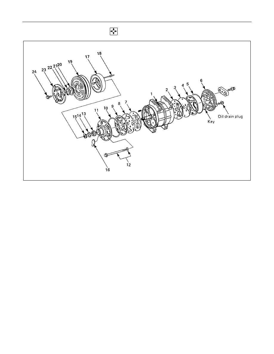
REASSEMBLY
Reassembly Steps
▲
1. Cylinder and shaft assembly
▲
2. Rear suction valve
▲
3. Rear valve plate
▲
4. Gasket
▲
5. O-ring
▲
6. Rear cylinder head
▲
7. Front suction valve
▲
8. Front valve plate
▲
9. Gasket
▲
10. O-ring
▲
11. Front cylinder head
▲
12. Through bolt with gasket
▲
13. Shaft seal assembly
14. Snap ring
▲
15. Shaft seal cover (If so equipped)
▲
16. Felt (If so equipped)
▲
17. Field coil
▲
18. Lead wire connector
▲
19. Pulley assembly
▲
20. Cover (If so equipped)
▲
21. Snap ring
▲
22. Shim(s)
▲
23. Drive plate
▲
24. Drive plate bolt
1-40 HEATING AND AIR CONDITIONING
Important Operation - Resassembly
1. Cylinder and Shaft Assembly
Clamp the cylinder shaft assembly in a vise. The rear side
of the cylinder shaft assembly must be facing up.
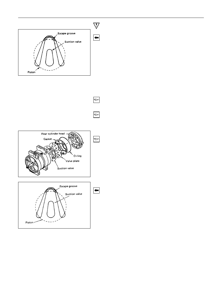
2. Rear Suction Valve
Install the suction valve by aligning it with the spring pin and
the cylinder valve relief grooves.
3. Rear Valve Plate
Install the valve plate to the suction valve by aligning it with
the spring pin.
Note:
Do not mix up the front and rear valve plates.
4. Gasket
1) Apply a coat of new compressor oil to the new gasket.
2) Install the gasket to the valve plate.
5. O-ring
6. Rear Cylinder Head
1) Apply a coat of new compressor oil to the new O-ring.
2) Install the O-ring to the rear cylinder head.
3) Install the rear cylinder head.
Tap the rear cylinder head into place with a plastic
hammer.
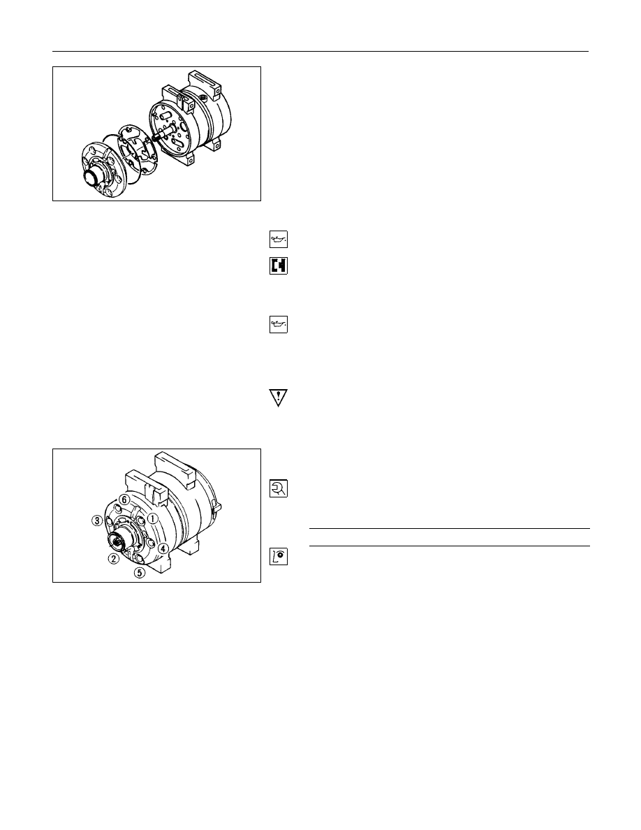
7. Front Suction Valve
Set the cylinder shaft assembly with the front side facing up.
Install the suction valve by aligning it with the spring pin and
the cylinder valve relief grooves.
HEATING AND AIR CONDITIONING 1-41
8. Front Valve Plate
Install the valve plate to the suction valve by aligning it with
the spring pin.
Note:
Do not mix up the front and rear valve plates.
9. Gasket
Apply new compressor oil to the new gasket.
Install the gasket to the valve plate by aligning it with the
spring pin.
10.O-ring
11.Front Cylinder Head
Apply a coat of new compressor oil to the new O-ring.
Install the O-ring to the front cylinder head.
Install the front cylinder head.
Tap the front cylinder head into place with a plastic
hammer.
Note:
When installing the cylinder head, be careful that the
end of the drive shaft does not damage the shaft seal
assembly surface in the cylinder head.
12.Through Bolt with Gasket
Gaskets cannot reused. Always replace new ones.
Tighten the bolts to the specified torque a little at a time in
the sequence shown in the illustration.
Through Bolt Torque
N
⋅
m (kg
⋅
m/lb
⋅
ft)
22 (2.2/16)
Rotate the compressor drive shaft two or three times to
make sure that it moves smoothly.
Нет комментариевНе стесняйтесь поделиться с нами вашим ценным мнением.
Текст