Isuzu D-Max / Isuzu Rodeo (TFR/TFS). Manual — part 136

6E–148
4JH1 ENGINE DRIVEABILITY AND EMISSIONS
Diagnostic Trouble Code (DTC) P0251 (Symptom Code E) (Flash Code 53)
Injection Pump Malfunction
Step
Action
Value(s)
Yes
No
1
Was the “On-Board Diagnostic (OBD) System Check”
performed?
—
Go to Step 2
Go to On Board
Diagnostic
(OBD) System
Check
2
1. Connect the Tech 2.
2. Review and record the failure information.
3. Select “F0: Read DTC Infor As Stored By ECU” in
“F0: Diagnostic Trouble Codes”.
Is the DTC P0251 (Symptom Code E) stored as
“Present Failure”?
—
Go to Step 3
Refer to
Diagnostic Aids
and Go to Step
3
3
1. Using the Tech 2, ignition “On” and engine “Off”.
2. Select “F1: Clear DTC Information” in “F0:
Diagnostic Trouble Codes” with the Tech 2 and
clear the DTC information.
3. Operate the vehicle and monitor the “F0: Read
DTC Infor As Stored By ECU” in the “F0:
Diagnostic Trouble Codes”.
Was the DTC P0251 (Symptom Code E) stored in this
ignition cycle?
—
Go to Step 4
Refer to
Diagnostic Aids
4
Was the DTC P1650 (Symptom Code A) or P1651
(Symptom Code B) stored at the same time?
—
Go to DTC
Chart P1650
(Symptom
Code A)
Go to Step 5
5
Is the ECM programmed with the latest software
release?
If not, download the latest software to the ECM using
the “SPS (Service Programming System)”.
Was the problem solved?
—
Verify repair
Go to Step 6
6
Substitute a known good ECM and recheck.
Was the problem solved?
IMPORTANT: The replacement ECM must be
programmed. Refer to section of the Service
Programming System (SPS) in this manual.
Following ECM programming, the immobiliser system
(if equipped) must be linked to the ECM. Refer to
section 11 “Immobiliser System-ECM replacement” for
the ECM/Immobiliser linking procedure.
—
Go to Step 7
Go to Step 8
7
Replace the ECM.
Is the action complete?
IMPORTANT: The replacement ECM must be
programmed. Refer to section of the Service
Programming System (SPS) in this manual.
Following ECM programming, the immobiliser system
(if equipped) must be linked to the ECM. Refer to
section 11 “Immobiliser System-ECM replacement” for
the ECM/Immobiliser linking procedure.
—
Verify repair
—
8
Replace the injection pump assembly.
Is the action complete?
—
Verify repair
—
4JH1 ENGINE DRIVEABILITY AND EMISSIONS
6E–149
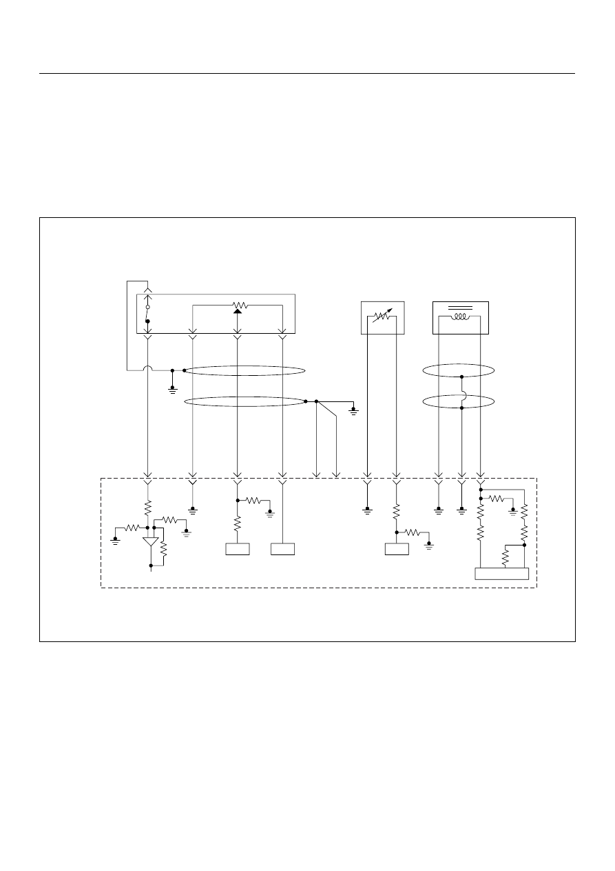
DIAGNOSTIC TROUBLE CODE (DTC) P0335 (SYMPTOM CODE B)
(FLASH CODE 43)CRANKSHAFT POSITION SENSOR CIRCUIT MALFUNCTION
DIAGNOSTIC TROUBLE CODE (DTC) P0335 (SYMPTOM CODE D)
(FLASH CODE 43) CRANKSHAFT POSITION SENSOR MALFUNCTION
DIAGNOSTIC TROUBLE CODE (DTC) P0335 (SYMPTOM CODE E)
(FLASH CODE 43) ENGINE SPEED INPUT CIRCUIT RANGE/PERFORMANCE
0.5
BLK
0.5
GRN/
BLK
69
0.5
RED
49
0.5
WHT
38
0.5
BLK
57
2.0
BLK
1
2.0
BLK
2
0.5
BLK/
PNK
93
0.5
GRY
ECT
Sensor
TPS &
Idle SW
89
0.5
WHT
98
101
0.5
RED
CKP
Sensor
90
IC
IC
IC
IC
Engine
Control
Module
(ECM)

6E–150
4JH1 ENGINE DRIVEABILITY AND EMISSIONS
Condition for setting the DTC and action taken when the DTC sets
Circuit Description
The CKP sensor is located on top of the flywheel
housing of the flywheel and fixed with a bolt. The CKP
sensor is of the magnet coil type. The inductive pickup
sensors four gaps in the flywheel exciter ring and is
used to determine the engine speed and engine
cylinder top dead center.
If the CKP sensor harness or sensor malfunction is
detected during engine run, DTC P0335 (Symptom
Code B) is stored.
If the CKP sensor harness or sensor malfunction is
detected during engine cranking, DTC P0335
(Symptom Code D) is stored.
If the CKP sensor signal frequency is excessively high
or engine over-running, DTC P0335 (Symptom Code E)
is stored.
Diagnostic Aids
An intermittent may be caused by the following:
• Poor connections.
• Misrouted harness.
• Rubbed through wire insulation.
• Broken wire inside the insulation.
Check for the following conditions:
• Poor connection at ECM-Inspect harness connectors
for backed out terminals, improper mating, broken
locks, improperly formed or damaged terminals, and
poor terminal to wire connection.
• Damaged harness-Inspect the wiring harness for
damage. If the harness appears to be OK, observe
the “Engine Speed” display on the Tech2 while
moving connectors and wiring harness related to the
sensor.
Diagnostic Trouble Code (DTC) P0335 (Symptom Code B) (Flash Code 43)
Crankshaft Position Sensor Circuit Malfunction
Diagnostic Trouble Code (DTC) P0335 (Symptom Code D) (Flash Code 43)
Crankshaft Position Sensor Malfunction
Flash
Code
Code
Symptom
Code
MIL
DTC Name
DTC Setting Condition
Fail-Safe (Back Up)
43
P0335
B
ON
Crankshaft Position Sensor
Circuit Malfunction
1. Engine speed is more than
665rpm.
2. CKP sensor pulse width
error.
When pump camshaft speed
sensor is OK:
ECM uses doubled pump cam-
shaft speed as substitute
engine speed.
When pump camshaft speed
sensor is not OK:
1. MAB (fuel cutoff solenoid
valve) is operated.
2. Desired injection quantity
becomes 0mg/strk.
D
ON
Crankshaft Position Sensor
Circuit Malfunction
1. No pump camshaft speed
sensor error.
2. “Crankshaft Position Sen-
sor Circuit Malfunction
(Symptom Code B)” is not
stored.
3. Engine speed is 0rpm.
4. Doubled pump camshaft
speed is more than 50rpm.
When pump camshaft speed
sensor is OK:
ECM uses doubled pump cam-
shaft speed as substitute
engine speed.
Other than pump camshaft
speed sensor is OK:
Fuel injection quantity is
reduced.
E
ON
Engine Speed Input Circuit
Range/Performance
Engine speed is more than
5700rpm.
When intermittent malfunction:
1. MAB (fuel cutoff solenoid
valve) is operated.
2. Desired injection quantity
becomes 0mg/strk.
When preliminary malfunction:
ECM uses doubled pump cam-
shaft speed as substitute
engine speed.
Step
Action
Value(s)
Yes
No
1
Was the “On-Board Diagnostic (OBD) System Check”
performed?
—
Go to Step 2
Go to On Board
Diagnostic
(OBD) System
Check
4JH1 ENGINE DRIVEABILITY AND EMISSIONS
6E–151
2
1. Connect the Tech 2.
2. Review and record the failure information.
3. Select “F0: Read DTC Infor As Stored By ECU” in
“F0: Diagnostic Trouble Codes”.
Is the DTC P0335 (Symptom Code B) or P0335
(Symptom Code D) stored as “Present Failure”?
—
Go to Step 3
Refer to
Diagnostic Aids
and Go to Step
3
3
1. Using the Tech 2, ignition “On” and engine “Off”.
2. Select “F1: Clear DTC Information” in “F0:
Diagnostic Trouble Codes” with the Tech 2 and
clear the DTC information.
3. Operate the vehicle and monitor the “F0: Read
DTC Infor As Stored By ECU” in the “F0:
Diagnostic Trouble Codes”.
Was the DTC P0335 (Symptom Code B) or P0335
(Symptom Code D) stored in this ignition cycle?
—
Go to Step 4
Refer to
Diagnostic Aids
and Go to Step
4
4
Check for poor/faulty connection at the CKP sensor or
ECM connector. If a poor/faulty connection is found,
repair the faulty terminal.
Was the problem found?
—
Verify repair
Go to Step 5
5
Visually check the CKP sensor. If a faulty installation is
found, repair as necessary.
Was the problem found?
—
Verify repair
Go to Step 6
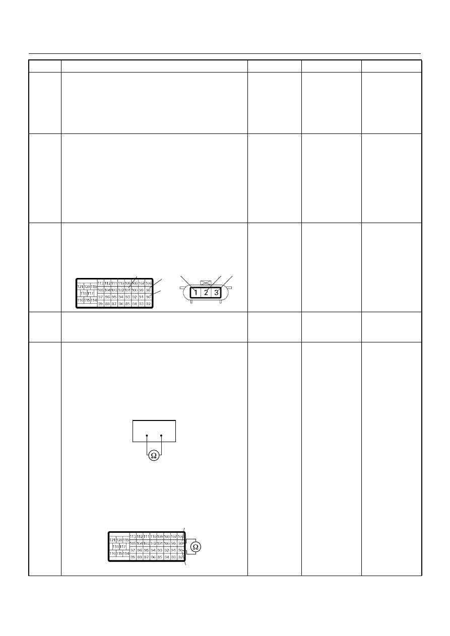
6
Using the DVM and check the CKP sensor circuit.
Breaker box is available:
1. Ignition “Off”, engine “Off”.
2. Install the breaker box as type A. (ECM
disconnected) Ref. Page 6E-73
3. Check the resistance of the CKP sensor.
Was the DVM indicated specified value?
Breaker box is not available:
1. Ignition “Off”, engine “Off”.
2. Disconnect the ECM connector.
3. Check the resistance of the CKP sensor.
Was the DVM indicated specified value?
Approximately
0.9k
Ω at 20°C
Go to Step 10
Go to Step 7
Step
Action
Value(s)
Yes
No
101
90
98
2
3
1
E-9
C-57(B)
90
98
90
98
C-57(B)
Нет комментариевНе стесняйтесь поделиться с нами вашим ценным мнением.
Текст