Isuzu D-Max / Isuzu Rodeo (TFR/TFS). Manual — part 137
6E–152
4JH1 ENGINE DRIVEABILITY AND EMISSIONS
7
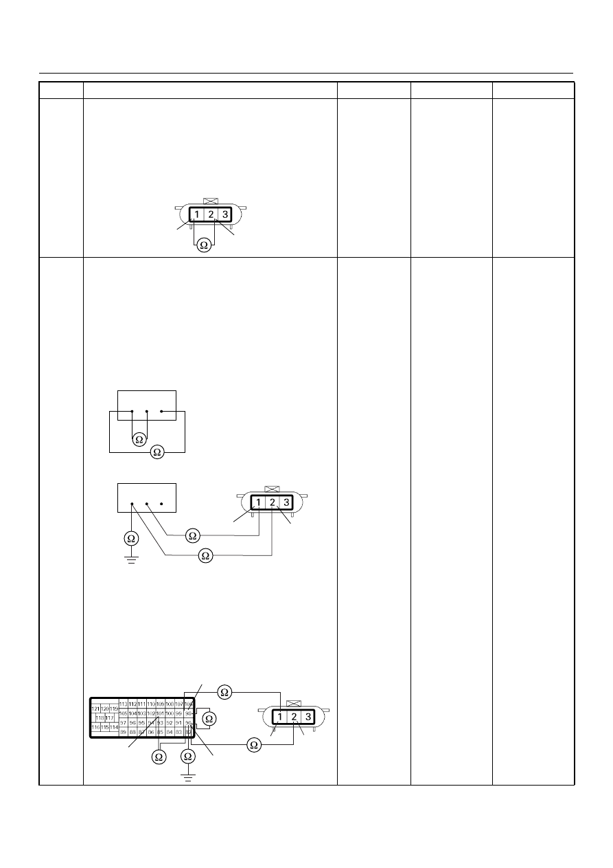
Using the DVM and check the CKP sensor circuit.
1. Ignition “Off”, engine “Off”.
2. Disconnect the CKP sensor connector.
3. Check the resistance of the CKP sensor.
Was the DVM indicated specified value?
Approximately
0.9k
Ω at 20°C
Go to Step 8
Go to Step 14
8
Using the DVM and check the CKP sensor circuit.
Breaker box is available:
1. Ignition “Off”, engine “Off”.
2. Install the breaker box as type A. (ECM
disconnected) Ref. Page 6E-73
3. Disconnect the CKP sensor connector.
4. Check the circuit for open, short to sensor wire or
short to ground circuit.
Was the problem found?
Breaker box is not available:
1. Ignition “Off”, engine “Off”.
2. Disconnect the ECM connector.
3. Disconnect the CKP sensor connector.
4. Check the circuit for open, short to sensor wire or
short to ground circuit.
Was the problem found?
—
Repair faulty
harness and
verify repair
Go to Step 9
Step
Action
Value(s)
Yes
No
1
2
E-9
90 98 101
90 98 101
1
2
E-9
101
98
90
2
1
E-9
C-57(B)
4JH1 ENGINE DRIVEABILITY AND EMISSIONS
6E–153
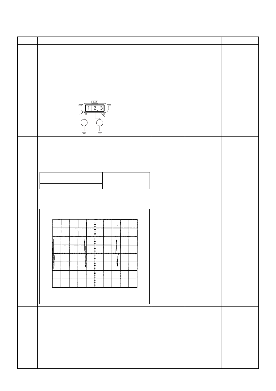
9
Using the DVM and check the CKP sensor circuit.
1. Ignition “On”, engine “Off”.
2. Disconnect the CKP sensor connector.
3. Check the circuit for short to power supply circuit.
If the DVM indicated out of specified value, repair
faulty harness and verify repair.
Is the action complete?
Less than 1V
Verify repair
—
10
Using the DVM and check the CKP sensor signal.
1. Ignition “On”, engine “On”.
2. Measure the CKP output voltage at the sensor
and ECM.
Does the tester indicate standard voltage?
If a oscilloscope is available, monitor the CKP sensor
signal. Does the oscilloscope indicate correct wave
form?
Go to Step 13
Go to Step 11
11
Remove the CKP sensor from the flywheel housing
and visually check.
Check for the following conditions.
• Objects sticking the CKP sensor.
• Objects sticking the CKP sensor pulser.
If a problem is found, repair as necessary.
Was the problem found?
—
Verify repair
Go to Step 12
12
Check the CKP sensor shield wire for open or short
circuit.
Was the problem found?
—
Repair faulty
harness and
verify repair
Go to Step 13
Step
Action
Value(s)
Yes
No
1
2
V
V
E-9
Measurement Point
Voltage (V) (AC Range)
At CKP sensor terminal 2 & 1
Approximately 1.0 V at
2000rpm
At ECM C57 connector 90 & 98
CKP Sensor Reference Wave Form
0V
→
Measurement Terminal: 90 (+) 98(-)
Measurement Scale: 20V/div
2.0ms/div
Measurement Condition: Engine speed at 2000rpm

6E–154
4JH1 ENGINE DRIVEABILITY AND EMISSIONS
13
Check any accessory parts which may cause electric
interference or magnetic interference.
Was the problem found?
—
Remove the
accessory parts
and verify repair
Go to Step 14
14
Substitute a known good CKP sensor and recheck.
Was the problem solved?
—
Go to Step 15
Go to Step 16
15
Replace the CKP sensor.
Was the problem solved?
—
Verify repair
Go to Step 16
16
Is the ECM programmed with the latest software
release?
If not, download the latest software to the ECM using
the “SPS (Service Programming System)”.
Was the problem solved?
—
Verify repair
Go to Step 17
17
Replace the ECM.
Is the action complete?
IMPORTANT: The replacement ECM must be
programmed. Refer to section of the Service
Programming System (SPS) in this manual.
Following ECM programming, the immobiliser system
(if equipped) must be linked to the ECM. Refer to
section 11 “Immobiliser System-ECM replacement” for
the ECM/Immobiliser linking procedure.
—
Verify repair
—
Step
Action
Value(s)
Yes
No

4JH1 ENGINE DRIVEABILITY AND EMISSIONS
6E–155
Diagnostic Trouble Code (DTC) P0335 (Symptom Code E) (Flash Code 43)
Engine Speed Input Circuit Range/Performance
Step
Action
Value(s)
Yes
No
1
Was the “On-Board Diagnostic (OBD) System Check”
performed?
—
Go to Step 2
Go to On Board
Diagnostic
(OBD) System
Check
2
1. Connect the Tech 2.
2. Review and record the failure information.
3. Select “F0: Read DTC Infor As Stored By ECU” in
“F0: Diagnostic Trouble Codes”.
Is the DTC P0335 (Symptom Code E) stored as
“Present Failure”?
—
Go to Step 3
Refer to
Diagnostic Aids
and Go to Step
3
3
1. Using the Tech 2, ignition “On” and engine “Off”.
2. Select “F1: Clear DTC Information” in “F0:
Diagnostic Trouble Codes” with the Tech 2 and
clear the DTC information.
3. Operate the vehicle and monitor the “F0: Read
DTC Infor As Stored By ECU” in the “F0:
Diagnostic Trouble Codes”.
Was the DTC P0335 (Symptom Code E) stored in this
ignition cycle?
—
Go to Step 4
Refer to
Diagnostic Aids
and Go to Step
4
4
Ask to the customer whether over-speed condition
such as miss-gear shifting etc. has been experienced
or not.
—
Explain the
reason of DTC
to the customer
Go to Step 5
5
Check for poor/faulty connection at the CKP sensor or
ECM connector. If a poor/faulty connection is found,
repair the faulty terminal.
Was the problem found?
—
Verify repair
Go to Step 6
101
90
98
2
3
1
E-9
C-57(B)
Нет комментариевНе стесняйтесь поделиться с нами вашим ценным мнением.
Текст