Isuzu D-Max / Isuzu Rodeo (TFR/TFS). Manual — part 1480
8-20 ELECTRICAL-BODY AND CHASSIS
Caution:
Do not attach the booster cable to the discharged battery
negative terminal.
11.Start the engine of the vehicle with the booster battery.
Check that all unnecessary electrical accessories are off.
12.Start the engine of the vehicle with the discharged battery.
13.Remove the jumper cables in the reverse order to which
they were attached.
Caution:
Be absolutely sure to remove the negative jumper cable
from the vehicle with the discharged battery first.
ELECTRICAL-BODY AND CHASSIS 8-21
READING THE CIRCUIT DIAGRAM
In this manual, each system has its own parts location illustration and circuit diagram.
And connector configurations used in the circuit diagram are shown at the end of this manual.
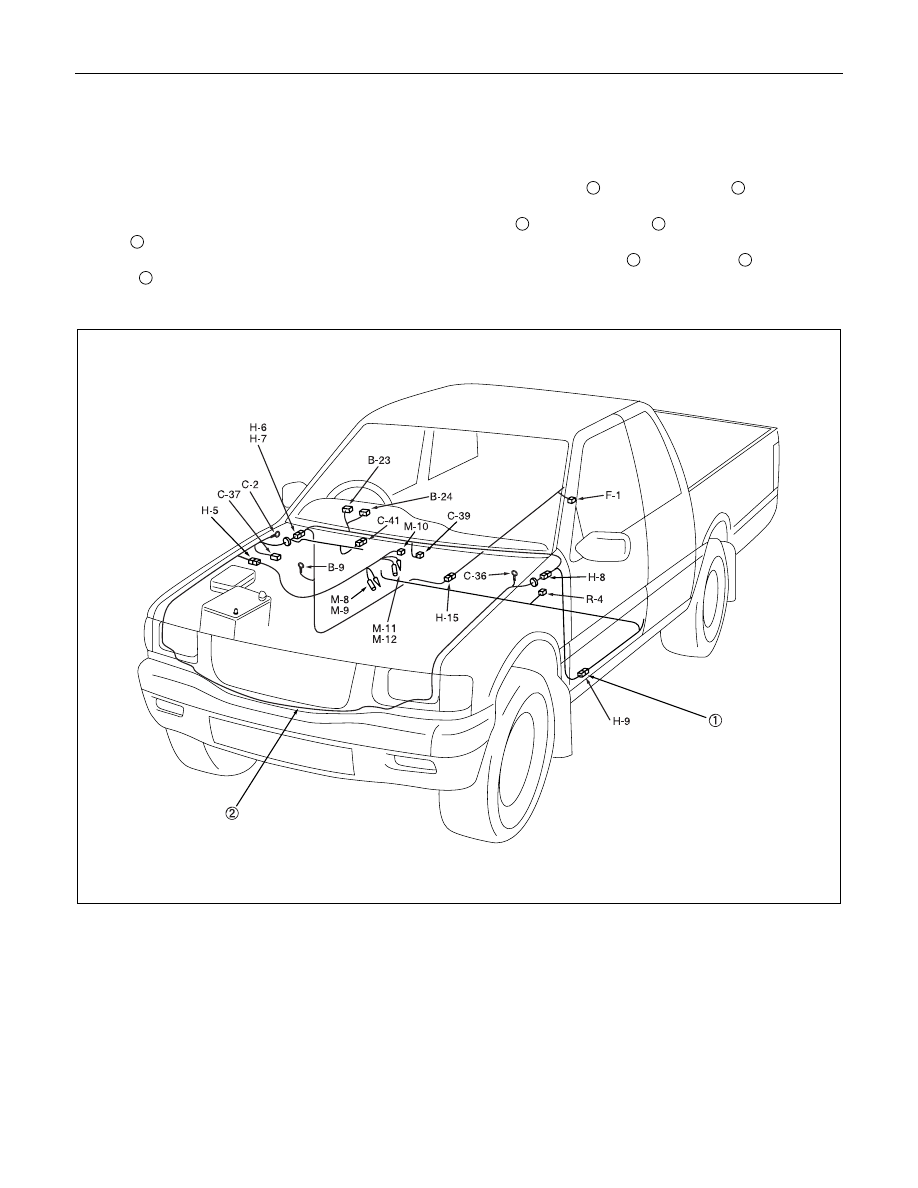
PARTS LOCATION: The parts location shows the location of the connectors
1
and the harnesses
2
used in the
each system.
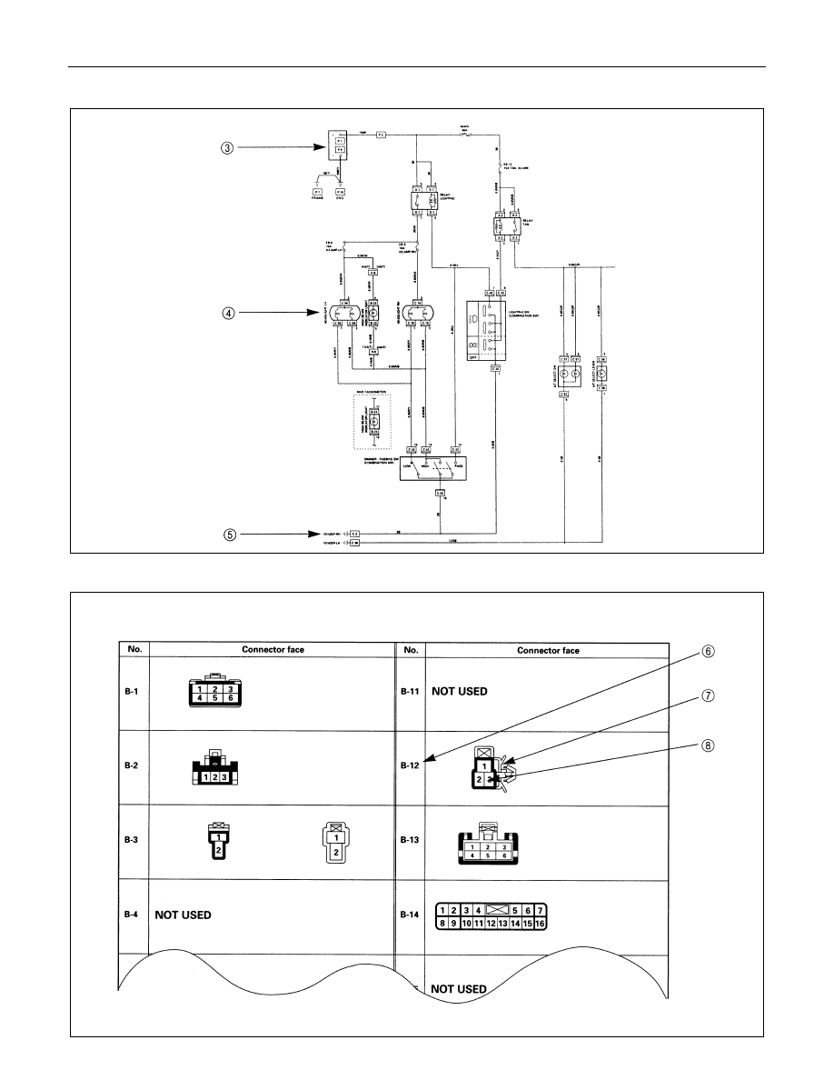
CIRCUIT DIAGRAM: The circuit diagram shows the power supply
3
, the load or loads
4
and the grounding
point(s)
5
.
CONNECTOR LIST: The connector configuration shows each connector's number
6
, configuration
7
and the pin
numbers
8
.
PARTS LOCATION
8-22 ELECTRICAL-BODY AND CHASSIS
CIRCUIT DIAGRAM
CONNECTOR LIST
CONNECTOR LIST
ELECTRICAL-BODY AND CHASSIS 8-23
MAIN DATA AND SPECIFICATIONS
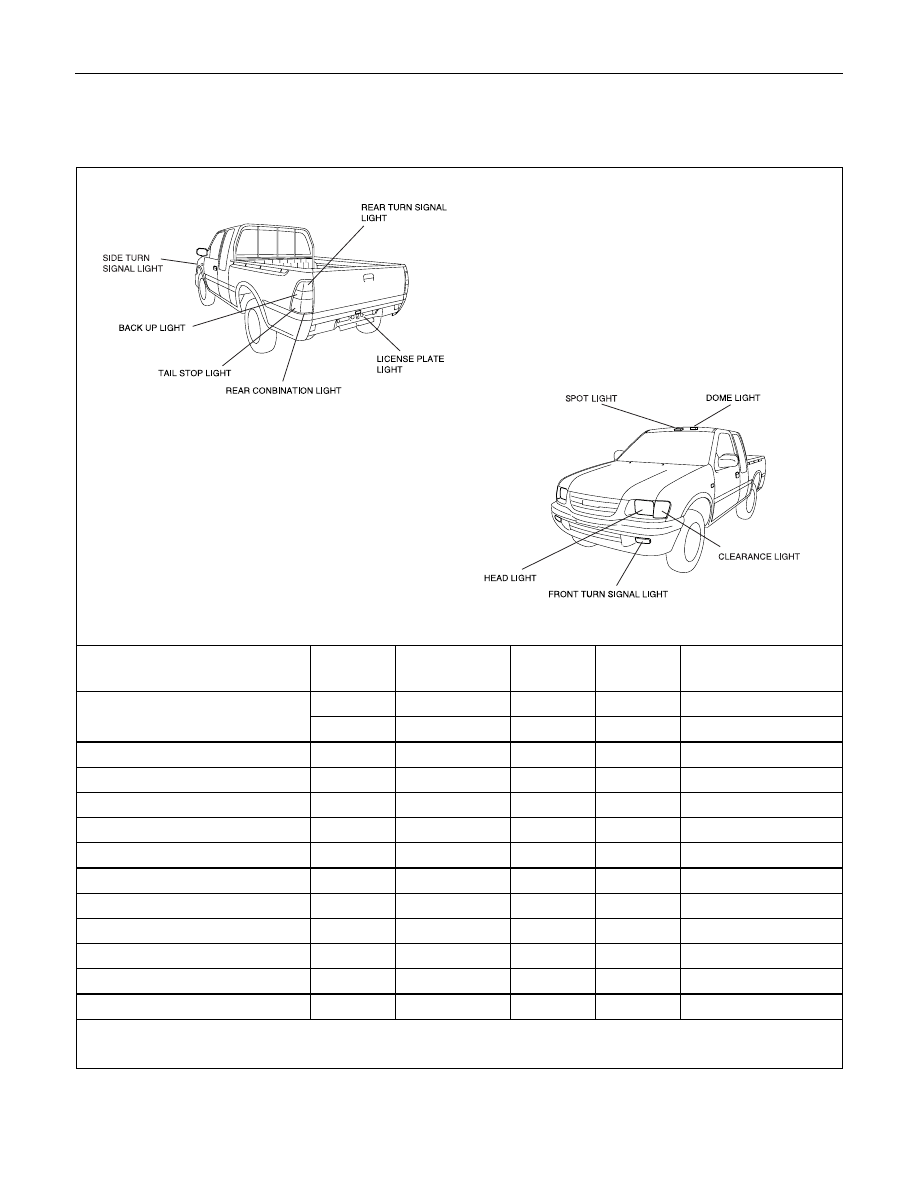
BULB SPECIFICATIONS
This illustration based on LHD
Light Name
Bulb No.
Rated Power
V-W
Number
of Bulbs
Lens
Color
Remarks
H4
12-60/55
2
White
Halogen
R2
12-45/40
2
White
Front turn signal light
-
12-23
2
Amber
Side turn signal light
W5W
12-5
2
Amber
Rear turn signal light
P21W
12-21
2
Amber
Tail and stop light
P21/5W
12-21/5
2
Red
Back up light
P21W
12-21
2
White
License plate light
W5W
12-5
1 or 2
White
Clearance light
W5W
12-5
2
White
A/C-Heater control light
-
12-0.7
1
-
Dome light
-
12-10
1
White
Spot light
-
12-5
2
White
Inspection light
-
12-5
1
White
Headlight
Нет комментариевНе стесняйтесь поделиться с нами вашим ценным мнением.
Текст