Isuzu D-Max / Isuzu Rodeo (TFR/TFS). Manual — part 1479
8-16 ELECTRICAL-BODY AND CHASSIS
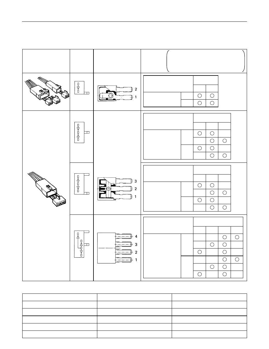
DIODE
Diode Specifications and Configurations
SHAPE
MARK/
COLOR
CONSTRUCTION
CHECKING
THERE SHOULD BE CONTINUITY IN
EITHER A OR B WHEN A CIRCUIT
TESTER IS CONNECTED WITH
DIODE TERMINAL
BLACK
2
1
CONNECTION
A
+
-
PATTERN
B
-
+
TERMINAL NO.
BLACK
3
2
1
-
+
CONNECTION
+
-
PATTERN
+
-
-
+
B
A
TERMINAL NO.
BLACK
3
2
1
-
+
CONNECTION
+
-
PATTERN
+
-
-
+
B
A
TERMINAL NO.
BLACK
4
3
2
1
+
-
A
-
+
CONNECTION
-
+
PATTERN
-
+
B
+
-
+
-
TERMINAL NO.
Maximum Rating (Temp.=25
°°°°C)
Items
Rating
Remarks
Peak reverse voltage
400V
Transient peak reverse voltage
500V
Average output current
1.5A
Temp.=40
°C
Working ambient temperature
-30
°C∼80°C
Storage temperature
-40
°C∼100ßC
ELECTRICAL-BODY AND CHASSIS 8-17
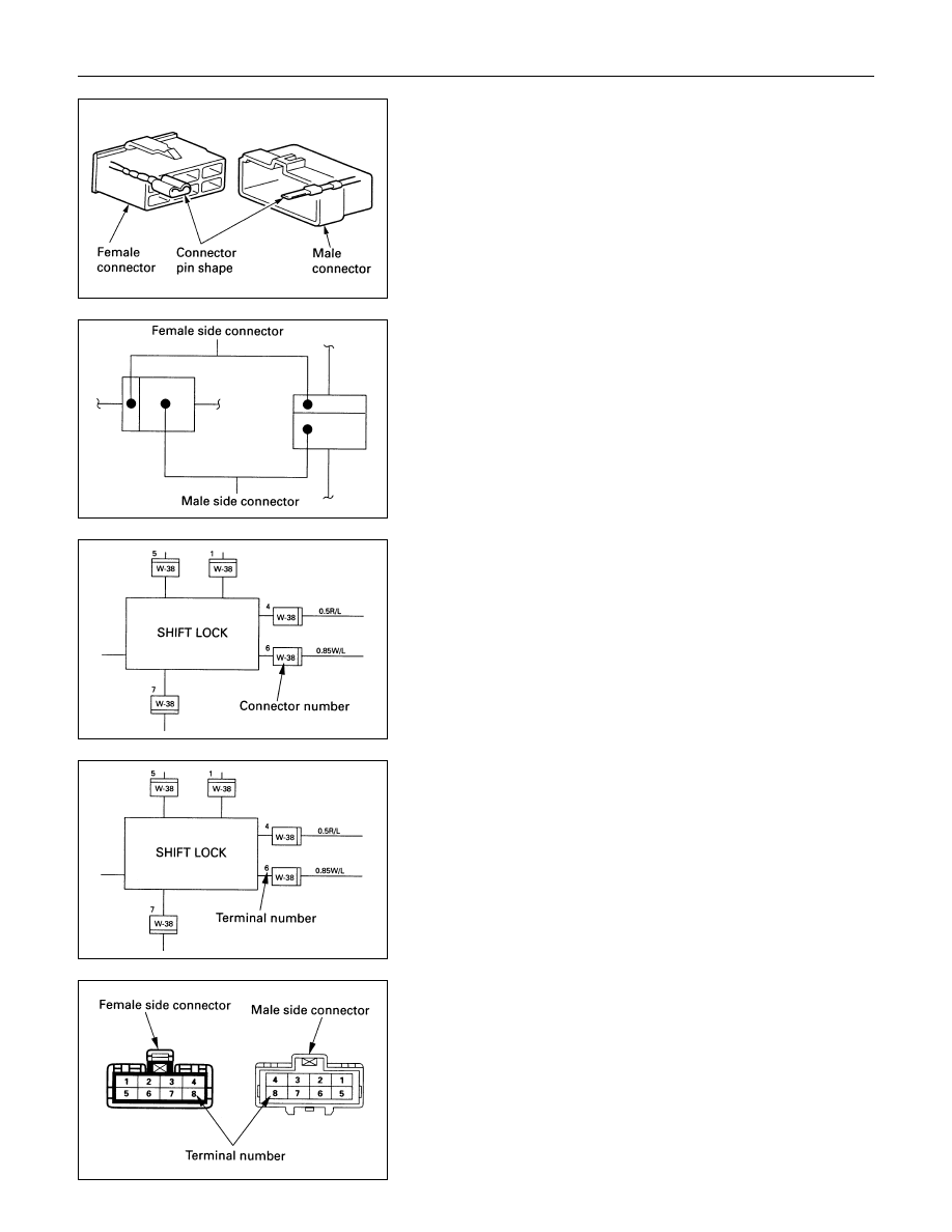
CONNECTOR
The connector pin shape determines whether the connector is
male or female.
The connector housing configuration does not determine
whether a connector is male or female.
The symbol illustrated in the figure is used as connector in the
circuit this section.
Connector is identified with a number.
The applicable terminal number is shown for each connector.
Connector terminal numbers are clearly shown.
Male side connector terminal numbers are in sequence from
upper right to lower left.
Female side connector terminal numbers are in sequence from
upper left to lower right.
NOTE:
For those connectors on which specific terminal numbers
on symbols are shown, the terminal numbers or symbols
are used in the circuit diagram, irrespective of the above
rule.
8-18 ELECTRICAL-BODY AND CHASSIS
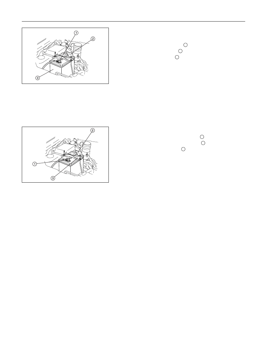
BATTERY
Inspection
1. Check the battery terminals
1
for corrosion.
2. Check the battery cables
2
for looseness.
3. Check the battery case
3
for cracks and other damage.
4. Check the battery electrolyte level.
If the electrolyte level is excessively low, the battery must be
replaced.
5. If the battery has a built-in hydrometer, perform the
following steps.
1) Carefully clean the battery upper surface.
2) Check the hydrometer.
The hydrometer design will vary with the battery
manufacturer.
Refer to the illustration shown on the battery.
Battery Replacement
1. Disconnect the battery ground cable
1
.
2. Disconnect the battery positive cable
2
.
3. Remove the battery clamp
3
.
4. Remove the battery
Caution:
It is important that the battery ground cable be removed
first.
Removing the battery positive cable first can result in a
short circuit.
Jump Starting the Engine with a Booster Battery
The following description assumes that you are using a booster
battery mounted on a second vehicle.
The listed steps (with some minor modifications) are also
applicable if you are using a naked booster battery or special
battery charging equipment.
ELECTRICAL-BODY AND CHASSIS 8-19
Caution:
Never push or tow the vehicle in an attempt to start it.
Extensive damage to the emission system and other
vehicle parts will result.
(only catalytic converter vehicle)
Treat both the discharged battery and the booster battery
with great care when using jumper cables.
Carefully follow the procedure outlined below.
Always be aware of the dangers of sparking.
Failure to follow the following procedure can result in:
a.Serious personal injury, specially to your eyes.
b.Extensive property damage from a battery explosion,
battery acid discharge, or electrical file.
c.Extensive damage to the electronic components of
both vehicles.
Do not use a 24 volt booster battery.
Serious damage to the vehicle's electrical system and
electronic components will result.
Jump Starting Procedure
1. Set the parking brake on both vehicles.
2. If one or both vehicles is equipped with a manual
transmission, place the gear shift in the "NEUTRAL"
position.
3. Turn off the ignition on both vehicles.
4. Turn off all vehicle lights and accessories.
5. Check the built-in hydrometer on the discharged Battery (If
so equipped).
If there is no hydrometer indication abandon the jump start
procedure.
6. Be sure that the two vehicles are not touching.
Attach the end of one jumper cable to the booster battery
positive terminal.
7. Attach the other end of the same cable to the discharged
battery positive terminal.
8. Once again, check that the booster battery has a 12 volt
rating.
9. Attach one end of the remaining booster cable to the
booster battery negative terminal.
10.Attach the other end of the booster cable to a solid ground
(such as the air conditioner compressor mounting bracket
or the alternator mounting bracket) in the engine room of
the vehicle with the discharged battery.
Be sure that the ground connection is at least 500 mm (20
in) from the discharged battery.
Нет комментариевНе стесняйтесь поделиться с нами вашим ценным мнением.
Текст