Isuzu D-Max / Isuzu Rodeo (TFR/TFS). Manual — part 44

4JA1-TC/4JH1-TC ENGINE DRIVEABILITY AND EMISSIONS
6E–171
Diagnostic Trouble Code (DTC) P0380 (Symptom Code 8) (Flash Code 66)
Glow Relay Circuit Voltage High
Step
Action
Value(s)
Yes
No
1
Was the “On-Board Diagnostic (OBD) System Check”
performed?
—
Go to Step 2
Go to On Board
Diagnostic
(OBD) System
Check
2
1. Connect the Tech 2.
2. Review and record the failure information.
3. Select “F0: Read DTC Infor As Stored By ECU” in
“F0: Diagnostic Trouble Codes”.
Is the DTC P0380 (Symptom Code 8) stored as
“Present Failure”?
—
Go to Step 3
Refer to
Diagnostic Aids
and Go to Step
3
3
1. Using the Tech 2, ignition “On” and engine “Off”.
2. Select “F1: Clear DTC Information” in “F0:
Diagnostic Trouble Codes” with the Tech 2 and
clear the DTC information.
3. Operate the vehicle and monitor the “F0: Read
DTC Infor As Stored By ECU” in the “F0:
Diagnostic Trouble Codes”.
Was the DTC P0380 (Symptom Code 8) stored in this
ignition cycle?
—
Go to Step 4
Refer to
Diagnostic Aids
4
Is the ECM programmed with the latest software
release?
If not, download the latest software to the ECM using
the “SPS (Service Programming System)”.
Was the problem solved?
—
Verify repair
Go to Step 5
5
Substitute a known good ECM and recheck.
Was the problem solved?
IMPORTANT: The replacement ECM must be
programmed. Refer to section of the Service
Programming System (SPS) in this manual.
Following ECM programming, the immobiliser system
(if equipped) must be linked to the ECM. Refer to
section 11 “Immobiliser System-ECM replacement” for
the ECM/Immobiliser linking procedure.
—
Go to Step 6
—
6
Replace the ECM.
Is the action complete?
IMPORTANT: The replacement ECM must be
programmed. Refer to section of the Service
Programming System (SPS) in this manual.
Following ECM programming, the immobiliser system
(if equipped) must be linked to the ECM. Refer to
section 11 “Immobiliser System-ECM replacement” for
the ECM/Immobiliser linking procedure.
—
Verify repair
—
6E–172
4JA1-TC/4JH1-TC ENGINE DRIVEABILITY AND EMISSIONS
DIAGNOSTIC TROUBLE CODE (DTC) P0381 (SUB CODE 4) (FLASH CODE 67)
GLOW PLUG INDICATOR CIRCUIT VOLTAGE LOW
DIAGNOSTIC TROUBLE CODE (DTC) P0381 (SUB CODE 8) (FLASH CODE 67)
GLOW PLUG INDICATOR CIRCUIT VOLTAGE HIGH
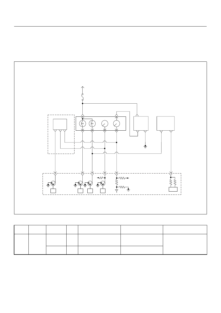
Condition for setting the DTC and action taken when the DTC sets
Circuit Description
The function of the glow time indicator lamp is to inform
the driver whether the glow system is activated.
When the lamp turned off, the engine can be started.
This does not imply that the glow plugs are no longer
activated.
In the after glow phase the lamp is not illuminated but
the glow plugs remain active for a certain period
depending on engine coolant temperature.
Diagnostic Aids
An intermittent may be caused by the following:
• Poor connections.
• Misrouted harness.
Flash
Code
Code
Symptom
Code
MIL
DTC Name
DTC Setting Condition
Fail-Safe (Back Up)
67
P0381
4
ON
Glow Plug Indicator Circuit
Voltage Low
Glow plug indicator circuit
open or short to ground cir-
cuit.
No fail-safe function.
8
ON
Glow Plug Indicator Circuit
Voltage High
Glow plug indicator circuit
short to voltage circuit.
Ignition
SW
Meter
15A
6 15
7
Batt
Batt
0.5
RED/
WHT
29
0.5
ORG/
BLU
43
0.5
BRN/
YEL
42
0.5
BLK/
RED
27
0.5
BLU/
WHT
0.5 BLU/BLK
68
0.5
WHT
2.0
BLK
35
VSS
0.85
YEL
Imnobiliser
Control Unit
7
8
0.5
BRN/
YEL
IC
0.85
YEL
Glow
Check
Engine
Tacho
Meter
Speed
Meter
A/T
TCM
µP
µP
µP
µP
Engine
Control
Module
(ECM)

4JA1-TC/4JH1-TC ENGINE DRIVEABILITY AND EMISSIONS
6E–173
• Rubbed through wire insulation.
• Broken wire inside the insulation.
Check for the following conditions:
• Poor connection at ECM-Inspect harness connectors
for backed out terminals, improper mating, broken
locks, improperly formed or damaged terminals, and
poor terminal to wire connection.
• Damaged harness-Inspect the wiring harness for
damage. If the harness appears to be OK, observe
the DTC P0381 display on the Tech2 while moving
connectors and wiring harnesses. A change in the
display will indicate the location of the fault.
Diagnostic Trouble Code (DTC) P0381 (Symptom Code 4) (Flash Code 67)
Glow Plug Indicator Circuit Voltage Low
Step
Action
Value(s)
Yes
No
1
Was the “On-Board Diagnostic (OBD) System Check”
performed?
—
Go to Step 2
Go to On Board
Diagnostic
(OBD) System
Check
2
1. Connect the Tech 2.
2. Review and record the failure information.
3. Select “F0: Read DTC Infor As Stored By ECU” in
“F0: Diagnostic Trouble Codes”.
Is the DTC P0381 (Symptom Code 4) stored as
“Present Failure”?
—
Go to Step 3
Refer to
Diagnostic Aids
and Go to Step
3
3
1. Using the Tech 2, ignition “On” and engine “Off”.
2. Select “F1: Clear DTC Information” in “F0:
Diagnostic Trouble Codes” with the Tech 2 and
clear the DTC information.
3. Operate the vehicle and monitor the “F0: Read
DTC Infor As Stored By ECU” in the “F0:
Diagnostic Trouble Codes”.
Was the DTC P0381 (Symptom Code 4) stored in this
ignition cycle?
—
Go to Step 4
Refer to
Diagnostic Aids
and Go to Step
4
4
1. Ignition “On”, engine “Off”.
2. Check the glow plug indicator lamp.
Does the lamp turn “On”?
—
Go to Step 5
Go to Step 6
5
1. Ignition “On”, engine “Off”.
2. Check the glow plug indicator lamp.
Does the lamp turn “Off”?
—
Go to Step 9
Go to Step 7
6
Check the glow plug indicator lamp bulb.
If the bulb is burnt out, repair as necessary.
Was the problem found?
—
Verify repair
Go to Step 7
6E–174
4JA1-TC/4JH1-TC ENGINE DRIVEABILITY AND EMISSIONS
7
Check for poor/faulty connection at the meter
connector and ECM connector. If a poor/faulty
connection is found, repair as necessary.
Was the problem found?
—
Verify repair
Go to Step 8
8
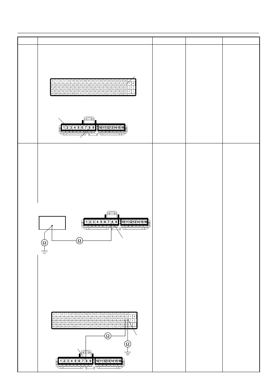
Using the DVM and check the glow time telltale circuit.
Breaker box is available:
1. Ignition “Off”, engine “Off”.
2. Install the breaker box as type A. (ECM
disconnected) Ref. Page 6E-81
3. Remove the meter connector.
4. Check the circuit for open or short to ground
circuit.
Was the problem found?
Breaker box is not available:
1. Ignition “Off”, engine “Off”.
2. Disconnect the ECM connector.
3. Remove the meter connector.
4. Check the circuit for open or short to ground
circuit.
Was the problem found?
—
Repair faulty
harness and
verify repair
Go to Step 9
Step
Action
Value(s)
Yes
No
43
2
8
B-24
C-56
8
B-24
43
43
8
B-24
C-56
Нет комментариевНе стесняйтесь поделиться с нами вашим ценным мнением.
Текст