Isuzu D-Max / Isuzu Rodeo (TFR/TFS). Manual — part 76
4JA1-TC/4JH1-TC ENGINE DRIVEABILITY AND EMISSIONS
6E–299
Diagnostic Trouble Code (DTC) P1613 (Symptom Code A) (Flash Code 56)
Immobiliser No or Wrong Signal
Step
Action
Value(s)
Yes
No
1
Was the “On-Board Diagnostic (OBD) System Check”
performed?
—
Go to Step 2
Go to On Board
Diagnostic
(OBD) System
Check
2
1. Connect the Tech 2.
2. Review and record the failure information.
3. Select “F0: Read DTC Infor As Stored By ECU” in
“F0: Diagnostic Trouble Codes”.
Is the DTC P1613 (Symptom Code A) stored as
“Present Failure”?
—
Go to Step 3
Refer to
Diagnostic Aids
and Go to Step
3
3
1. Using the Tech 2, ignition “On” and engine “Off”.
2. Select “F1: Clear DTC Information” in “F0:
Diagnostic Trouble Codes” with the Tech 2 and
clear the DTC information.
3. Operate the vehicle and monitor the “F0: Read
DTC Infor As Stored By ECU” in the “F0:
Diagnostic Trouble Codes”.
Was the DTC P1613 (Symptom Code A) stored in this
ignition cycle?
—
Go to Step 4
Refer to
Diagnostic Aids
and Go to Step
4
4
1. Using the Tech 2, ignition “On” and engine “Off”.
2. Select “Immobiliser” in the system selection menu
“Body”.
3. Select “Read DTC Info Ordered By Priority” in the
“Diagnositic Trouble Code”.
Was the any DTC's B**** stored in this ignition cycle?
—
Refer to
“Immobiliser
Workshop
Manual” & Go
to DTC Chart
B****
Go to Step 5
5
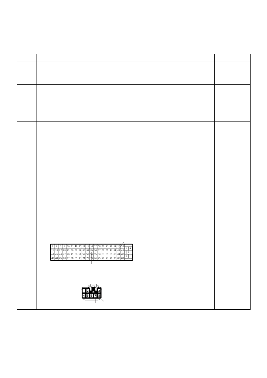
Check for poor/faulty connection at the immobiliser
control unit connector or ECM connector. If a poor/
faulty connection is found, repair as necessary.
Was the problem found?
—
Verify repair
Go to Step 6
42
35
7
8
C-56
B-68
6E–300
4JA1-TC/4JH1-TC ENGINE DRIVEABILITY AND EMISSIONS
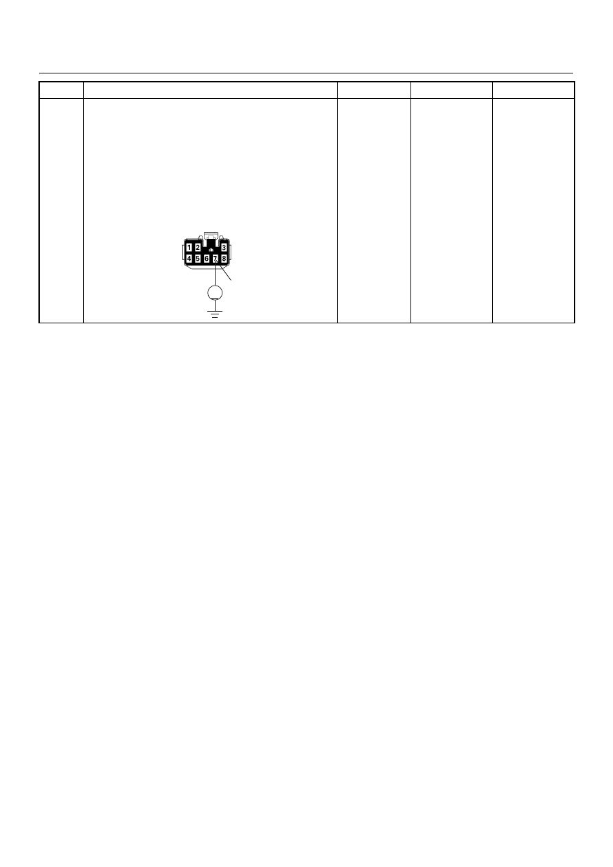
6
Using the DVM and check the “CHECK ENGINE”
lamp circuit.
1. Ignition “Off”, engine “Off”.
2. Disconnect the meter connector and immobiliser
control unit connector.
3. Ignition “On”.
4. Check the circuit for short to power supply circuit.
Was DVM indicated specified value?
Less than 1V
Go to Step 7
Repair faulty
harness and
verify repair
Step
Action
Value(s)
Yes
No
7
V
B-68
4JA1-TC/4JH1-TC ENGINE DRIVEABILITY AND EMISSIONS
6E–301
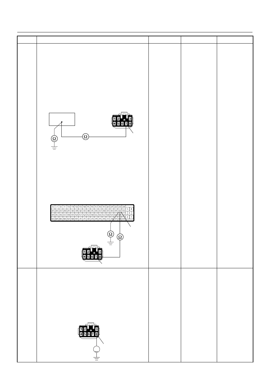
7
Using the DVM and check the “CHECK ENGINE”
lamp circuit.
Breaker box is available:
1. Ignition “Off”, engine “Off”.
2. Install the breaker box as type A. (ECM
disconnected) Ref. Page 6E-81
3. Disconnect the immobiliser control unit connector.
4. Check the circuit for open or short to ground
circuit.
Was the problem found?
Breaker box is not available:
1. Ignition “Off”, engine “Off”.
2. Disconnect the the immobiliser control unit
connector and ECM connector.
3. Check the circuit for open or short to ground
circuit.
Was the problem found?
—
Repair faulty
harness and
verify repair
Go to Step 8
8
Using the DVM and check the ECM and immobiliser
control unit communication circuit.
1. Ignition “Off”, engine “Off”.
2. Disconnect the immobiliser control unit connector.
3. Ignition “On”.
4. Check the circuit for short to power supply circuit.
Was the DVM indicated specified value?
Less than 1V
Go to Step 9
Repair faulty
harness and
verify repair
Step
Action
Value(s)
Yes
No
42
7
B-68
42
7
C-56
B-68
8
V
B-68
6E–302
4JA1-TC/4JH1-TC ENGINE DRIVEABILITY AND EMISSIONS
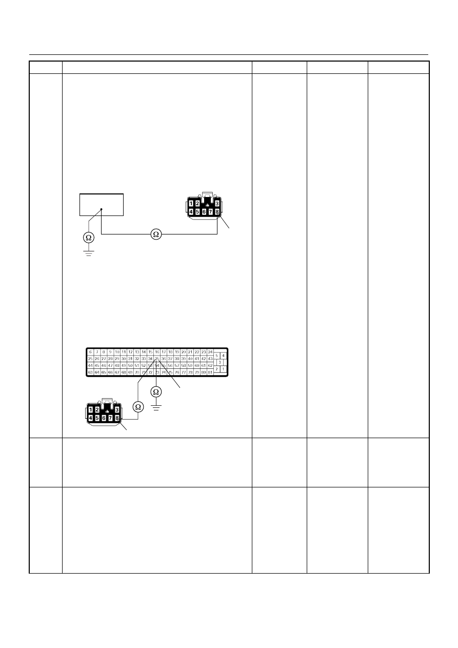
9
Using the DVM and check the ECM and immobiliser
control unit communication circuit.
Breaker box is available:
1. Ignition “Off”, engine “Off”.
2. Install the breaker box as type A. (ECM
disconnected) Ref. Page 6E-81
3. Disconnect the immobiliser control unit connector.
4. Check the circuit for open or short to ground
circuit.
Was the problem found?
Breaker box is not available:
1. Ignition “Off”, engine “Off”.
2. Disconnect the the immobiliser control unit
connector and ECM connector.
3. Check the circuit for open or short to ground
circuit.
Was the problem found?
—
Repair faulty
harness and
verify repair
Go to Step 10
10
Is the ECM programmed with the latest software
release?
If not, download the latest software to the ECM using
the “SPS (Service Programming System)”.
Was the problem solved?
—
Verify repair
Go to Step 11
11
Replace the ECM.
Is the action complete?
IMPORTANT: The replacement ECM must be
programmed. Refer to section of the Service
Programming System (SPS) in this manual.
Following ECM programming, the immobiliser system
(if equipped) must be linked to the ECM. Refer to
section 11 “Immobiliser System-ECM replacement” for
the ECM/Immobiliser linking procedure.
—
Verify repair
—
Step
Action
Value(s)
Yes
No
35
8
B-68
35
8
C-56
B-68
Нет комментариевНе стесняйтесь поделиться с нами вашим ценным мнением.
Текст