Isuzu D-Max / Isuzu Rodeo (TFR/TFS). Manual — part 1230
8-260 ELECTRICAL-BODY AND CHASSIS
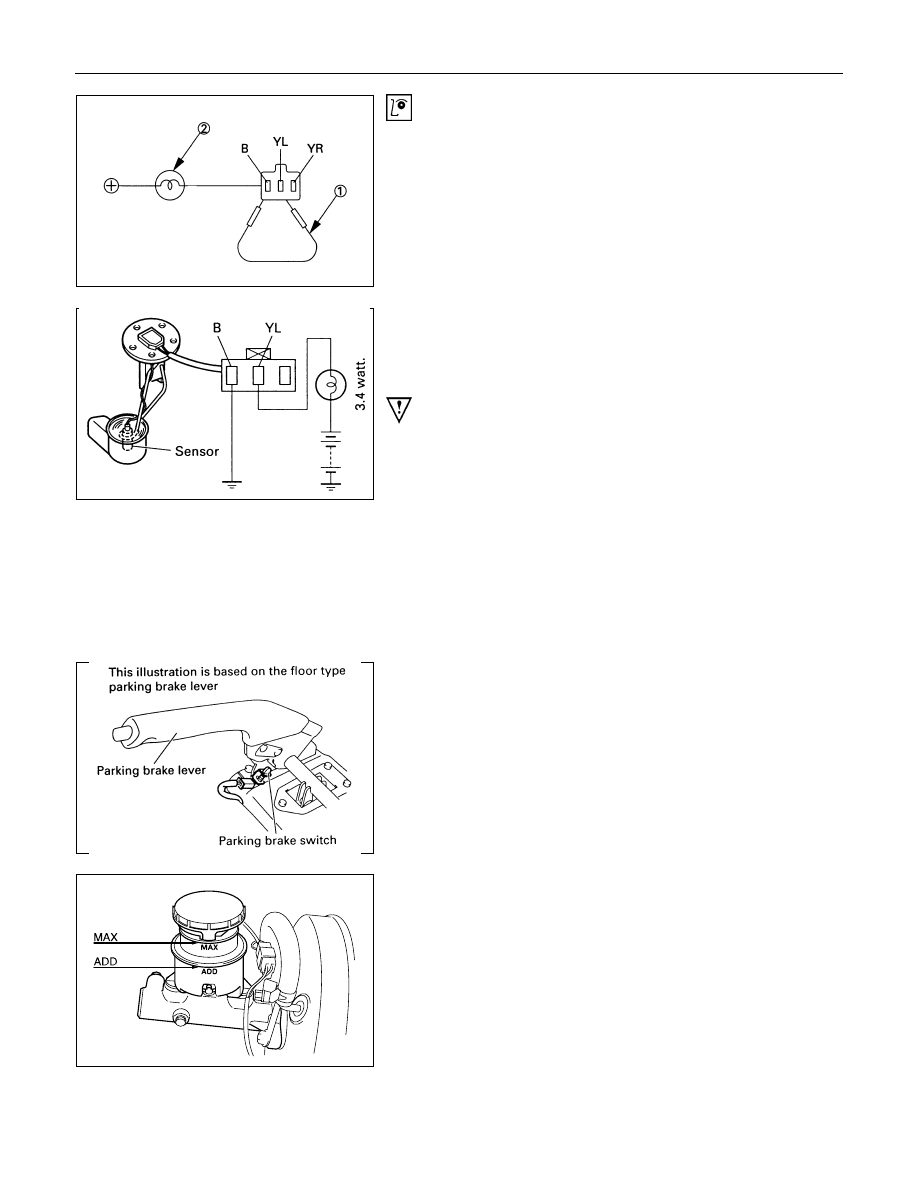
Low Fuel Indicator Light Inspection
1. Disconnect the fuel tank unit wire connector.
2. Connect between terminal (YL) and (B).
3. Turn the key switch on. Check that the bulb lights.
If operation is not correct, remove and check the bulb or circuit.
Check level sensor operation
1. Remove the fuel tank unit.
2. Apply battery voltage between terminal (YL) and (B) through
a 3.4 watt bulb. Check that the bulb lights.
Note:
It will take a short time for the bulb light.
3. Submerge the sensor in fuel. Check that the bulb goes out.
If operation is not correct, replace the fuel tank unit.
BRAKE SYSTEM WARNING LIGHT
The brake system warning light comes on while the parking
brake is set and the starter key is ON position.
Note:
The parking brake indicator light circuit is designed to
prevent driving of the vehicle with the parking brake on.
It does not indicate the condition of the parking brake
system.
The parking brake switch is in parallel with the brake fluid
switch.
The brake system warning light also comes on when reservoir
brake fluid level falls below the specified limit with the parking
brake released and the starter switch is ON position.
ELECTRICAL-BODY AND CHASSIS 8-261
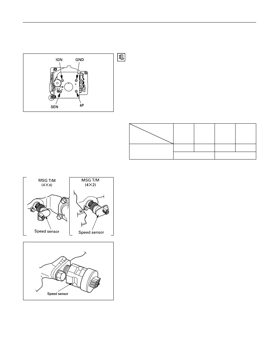
VEHICLE SPEED SENSOR
(INCORPORATED IN THE
SPEEDOMETER)
Vehicle Speed Sensor Inspection
Remove the speedometer from the meter assembly and
measure the resistance value between the terminals.
Speed Sensor Resistance
Tester
Terminal
terminal
symbol
Red (+) Black (-) Black (-) Red (+)
4P
GND
4P
GND
13.5 - 16.5k
¥
4P - GND
Note: Use the analog type circuit tester.
VEHICLE SPEED SENSOR (INSTALLED
ON THE TRANSMISSION)
The speed sensor is installed on the rear portion of the
transmission.
The number of pulses generated is four pulses per one rotation
of the pinion shaft.
MUA T/M

8-262 ELECTRICAL-BODY AND CHASSIS
Vehicle Speed Sensor Inspection
1. Connect the vehicle speed sensor connector 1
M-10
(Diesel engine: 1
E-44
) to the battery (+) terminal and 2
M-10
(Diesel engine: 2
E-44
) to the (-) terminal.
2. Connect a resistance of 1.3K ohm to 5K ohm (1/4 W or
more) between connectors 1
M-10
. (Diesel engine: 1
E-44
)
and 3
M-10
(Diesel engine: 3
E-44
)
CAUTION:
Be extremely careful not to connect the battery (+)
terminal to the connector 3
M-10
(Diesel engine: 3
E-44
).
This may damage the vehicle speed sensor.
3. Rotate the shaft of the vehicle speed sensor slowly and
measure the voltage at the both ends with a digital tester.
The voltage, with one rotation of shaft fluctuates four times in
the following range: 10 to 14V - 2V or less.
ELECTRICAL-BODY AND CHASSIS 8-263
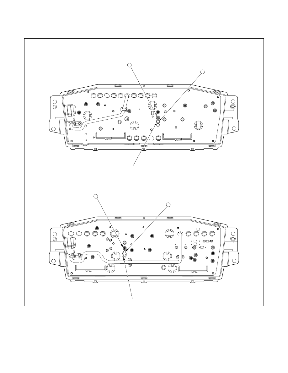
Timing Belt Indicator Light Reset Procedure (4 Diesel Engine)
Masking tape
A
B
W/ Tachometer
Masking tape
W/O Tachometer
A
B
Timing belt must be replaced after 100,000 km of vehicle operation.
When the odometer reading reaches 100,000 km, the timing belt indicator light will turn on to remind the driver to
change the timing belt.
After replacing the timing belt, the timing belt indicator light must be reset to remind the driver to replace the timing
belt after the next 100,000 km.
Нет комментариевНе стесняйтесь поделиться с нами вашим ценным мнением.
Текст