Isuzu D-Max / Isuzu Rodeo (TFR/TFS). Manual — part 161
6E–248
4JH1 ENGINE DRIVEABILITY AND EMISSIONS
• Damaged harness-Inspect the wiring harness for
damage. If the harness appears to be OK, observe
the “Engine Speed” display on the Tech2 while
moving connectors and wiring harness related to the
sensor.
Diagnostic Trouble Code (DTC) P1335 (Symptom Code A) (Flash Code 43)
Engine Speed Output Circuit Malfunction
Step
Action
Value(s)
Yes
No
1
Was the “On-Board Diagnostic (OBD) System Check”
performed?
—
Go to Step 2
Go to On Board
Diagnostic
(OBD) System
Check
2
1. Connect the Tech 2.
2. Review and record the failure information.
3. Select “F0: Read DTC Infor As Stored By ECU” in
“F0: Diagnostic Trouble Codes”.
Is the DTC P1335 (Symptom Code A) stored as
“Present Failure”?
—
Go to Step 3
Refer to
Diagnostic Aids
and Go to Step
3
3
1. Using the Tech 2, ignition “On” and engine “Off”.
2. Select “F1: Clear DTC Information” in “F0:
Diagnostic Trouble Codes” with the Tech 2 and
clear the DTC information.
3. Operate the vehicle and monitor the “F0: Read
DTC Infor As Stored By ECU” in the “F0:
Diagnostic Trouble Codes”.
Was the DTC P1335 (Symptom Code A) stored in this
ignition cycle?
—
Go to Step 4
Refer to
Diagnostic Aids
and Go to Step
4
4
Was the DTC P0335 (Symptom Code B) or P0335
(Symptom Code D) stored at the same time?
—
Go to DTC
Chart P0335
(Symptom
Code B)
(Symptom
Code C)
Go to Step 5
5
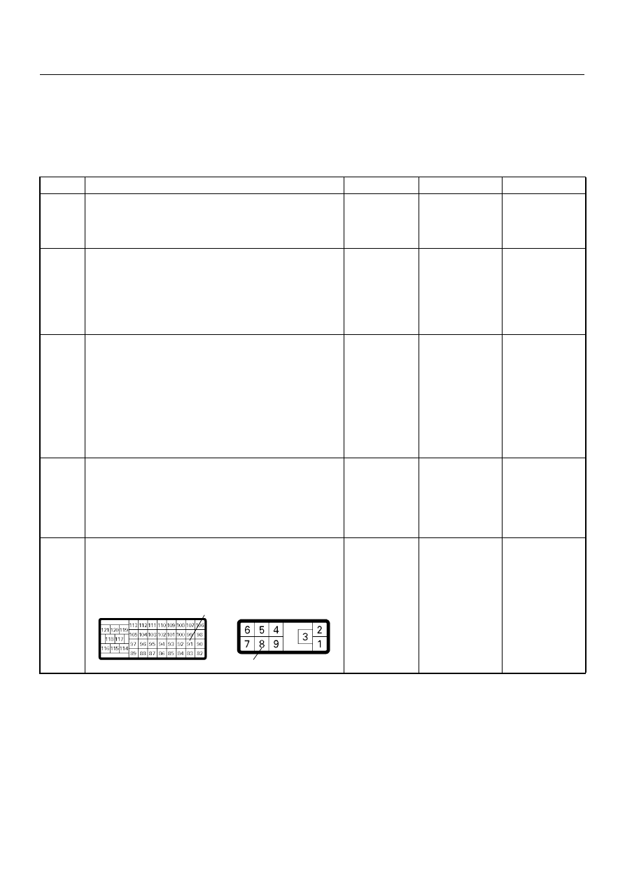
Check for poor/faulty connection at the ECM or PSG
(pump control unit) connector. If a poor/faulty
connection is found, repair the faulty terminal.
Was the problem found?
—
Verify repair
Go to Step 6
91
8
C-57(B)
E-6
4JH1 ENGINE DRIVEABILITY AND EMISSIONS
6E–249
6
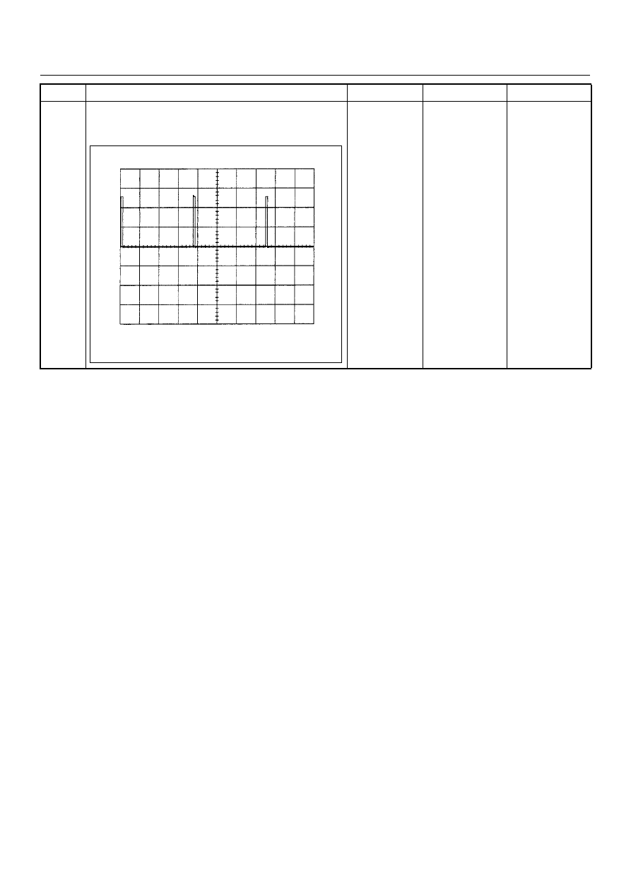
If a oscilloscope is available, monitor the CKP sensor
output signal. Does the oscilloscope indicate correct
wave form?
—
Go to Step 13
Not available:
Go to Step 7
Fixed at low: Go
to Step 7
Fixed at High:
Go to Step 8
Step
Action
Value(s)
Yes
No
CKP Sensor Output Reference Wave Form
0V
→
Measurement Terminal: 91 (+) 1 (-)
Measurement Scale: 5.0V/div
2.0ms/div
Measurement Condition: Engine speed at 2000rpm
6E–250
4JH1 ENGINE DRIVEABILITY AND EMISSIONS
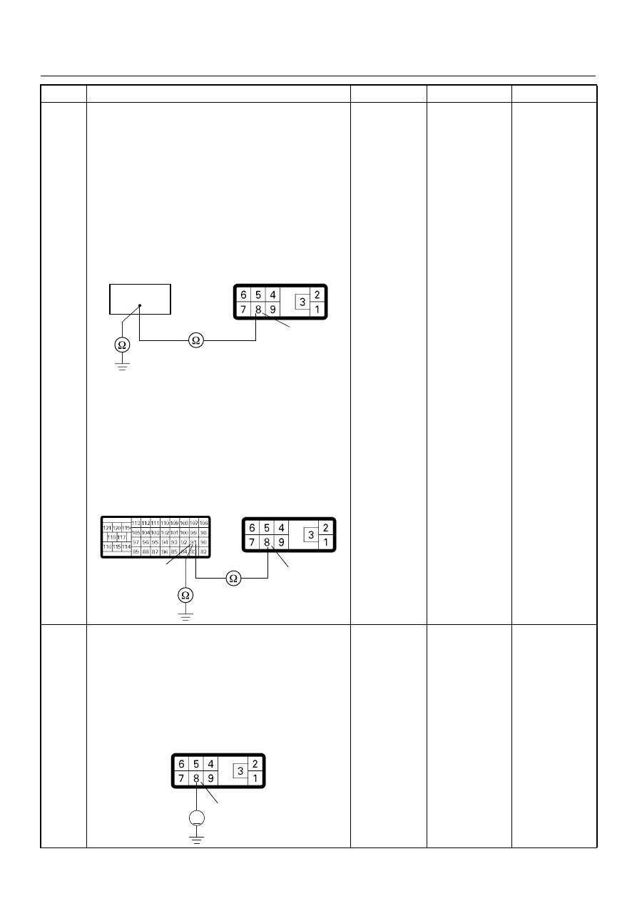
7
Using the DVM and check the CKP sensor output
circuit.
Breaker box is available:
1. Ignition “Off”, engine “Off”.
2. Install the breaker box as type A. (ECM
disconnected) Ref. Page 6E-73
3. Disconnect the PSG (pump control unit)
connector.
4. Check the circuit for open or short to ground
circuit.
Was the problem found?
Breaker box is not available:
1. Ignition “Off”, engine “Off”.
2. Disconnect the ECM connector.
3. Disconnect the PSG (pump control unit)
connector.
4. Check the circuit for open or short to ground
circuit.
Was the problem found?
—
Repair faulty
harness and
verify repair
Go to Step 8
8
Using the DVM and check the CKP sensor output
circuit.
1. Ignition “On”, engine “Off”.
2. Disconnect the PSG (pump control unit)
connector.
3. Check the circuit for short to power supply circuit.
Was the DVM indicated specified value?
Less than 1V
Go to Step 9
Repair faulty
harness and
verify repair
Step
Action
Value(s)
Yes
No
91
8
E-6
91
8
C-57(B)
E-6
8
V
E-6

4JH1 ENGINE DRIVEABILITY AND EMISSIONS
6E–251
9
Check any accessory parts which may cause electric
interference or magnetic interference.
Was the problem found?
—
Remove the
accessory parts
and verify repair
Go to Step 10
10
Is the ECM programmed with the latest software
release?
If not, download the latest software to the ECM using
the “SPS (Service Programming System)”.
Was the problem solved?
—
Verify repair
Go to Step 11
11
Substitute a known good ECM and recheck.
Was the problem solved?
IMPORTANT: The replacement ECM must be
programmed. Refer to section of the Service
Programming System (SPS) in this manual.
Following ECM programming, the immobiliser system
(if equipped) must be linked to the ECM. Refer to
section 11 “Immobiliser System-ECM replacement” for
the ECM/Immobiliser linking procedure.
—
Go to Step 12
Go to Step 13
12
Replace the ECM.
Is the action complete?
IMPORTANT: The replacement ECM must be
programmed. Refer to section of the Service
Programming System (SPS) in this manual.
Following ECM programming, the immobiliser system
(if equipped) must be linked to the ECM. Refer to
section 11 “Immobiliser System-ECM replacement” for
the ECM/Immobiliser linking procedure.
—
Verify repair
—
13
Replace the injection pump assembly.
Is the action complete?
—
Verify repair
—
Step
Action
Value(s)
Yes
No
Нет комментариевНе стесняйтесь поделиться с нами вашим ценным мнением.
Текст