Isuzu D-Max / Isuzu Rodeo (TFR/TFS). Manual — part 667

7A1 – 168 AUTOMATIC TRANSMISSION (4L30-E)
25. Second and Third Clutch Assemblies
1) Carefully align second clutch plates inner tangs.
2) Install thrust washer, tangs pointing downward,
locating tang positioned in slot on second clutch
hub.
NOTE:
Use petroleum jelly to hold thrust washer in place.
3) Install third clutch and intermediate shaft
assembly into the second clutch drum.
4) Install second and third clutch assemblies into the
main case. Twist output shaft and clutch
assemblies to insure proper fit.
5) Install pressure plate with lip side up, tang facing
valve body face.
6) Install reverse clutch plates. Start with a steel
plate and alternate with lined plates.
7) Install waved clutch plate, center tang facing valve
body side.
5-8840-2262-0
Second clutch end play measurement
1) Install the gaging tool on the case flange and
against the intermediate shaft.
2) Position the inner shaft of the gaging tool against
the thrust surface of the second clutch hub.
3) Tighten thumb screw. Remove the tool.
4) Fit the spacer ring on the inner shaft of the tool.
5) Measure gap (“G”). Select appropriate size
washer as the chart specified.
Selective washer gaging tool: 5-8840-2262-0
(J-23085-A)
Selective Thrust Washer
DIM. “G” mm(in)
Color
1.53 - 1.63 (0.060 - 0.064)
YELLOW
1.72 - 1.82 (0.068 - 0.072)
RED
1.91 - 2.01 (0.075 - 0.079)
BLACK
2.10 - 2.20 (0.083 - 0.087)
NATURAL
2.29 - 2.39 (0.090 - 0.094)
GREEN
2.48 - 2.58 (0.098 - 0.102)
BLUE
FOLLOWING THE PROCEDURE SHOULD
RESULT IN FINAL END-PLAY FROM
0.36mm TO 0.79 mm (.014” TO .031”)
247RW007
AUTOMATIC TRANSMISSION (4L30-E) 7A1 – 169
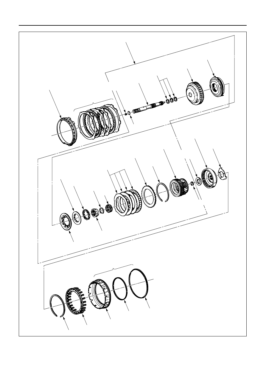
17. Fourth clutch retainer
18. Fourth clutch plates
18. Turbine shaft and overrun clutch
Turbine shaft
Turbine shaft oil seal ring
Overrun clutch drum
Overrun clutch piston
2. O-ring
Overrun clutch relase
spring retainer
Roller clutch
Snap ring
Sun gear
Clutch plate
Backing plate
Snap ring
OD
carrier assembly
20. OD
internal gear
21. Thrust
washer
Diaphragm spring
Overrun roller clutch cam
24. Fourth clutch piston
23. Snap ring
23. Retainer and spring assembly
Fourth clutch piston
Piston seal
Piston seal
19. Thrust
bearing
Snap ring
Ratainer and
ball assembly
7A1 – 170 AUTOMATIC TRANSMISSION (4L30-E)
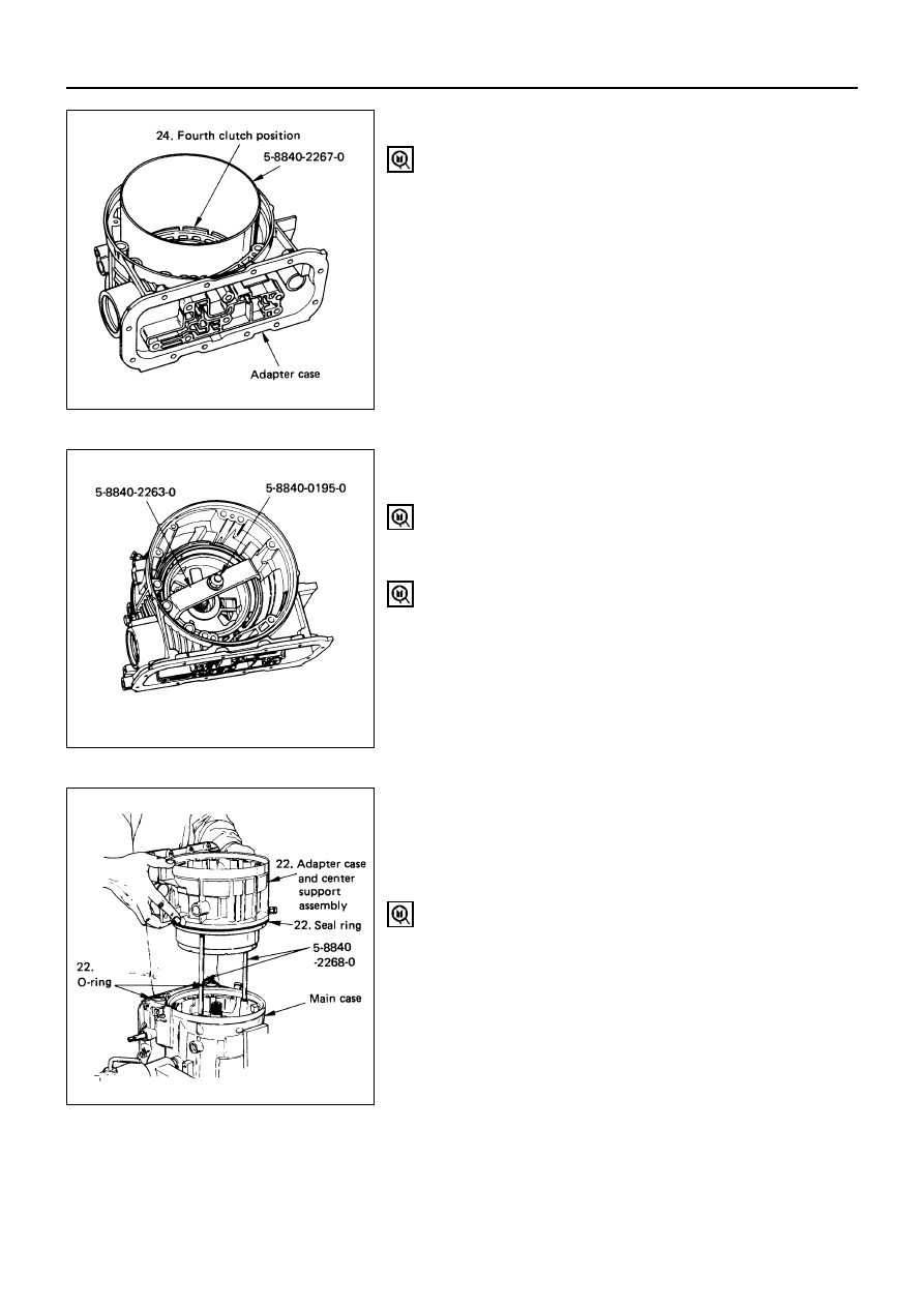
23. Fourth Clutch Spring Retainer
1) Install retainer and spring assembly.
2) Install snap ring in adapter case.
3) Install compressor.
4) Compress retainer and spring assembly.
5) Seat snap ring in groove.
6) Remove compressor.
Fourth clutch spring compressor: 5-8840-0195-0
(J-23327) and 5-8840-2263-0 (J-23327-90)
22. Adapter Case and Center Support Assembly
1) Install selective washer using petroleum jelly.
2) Install two O-ring seals in main case and adapter
case/main case seal ring.
3) Install guide pins.
4) Install adapter case complete to main case.
Guide pin: 5-8840-2268-0 (J-38588)
24. Fourth Clutch Piston
1) Inspect piston seals and replace if necessary.
2) Lubricate fitter and install on fourth clutch piston.
3) Install fourth clutch piston in adapter case.
4) Remove fitter.
Fourth clutch piston fitter: 5-8840-2267-0 (J-38554)

AUTOMATIC TRANSMISSION (4L30-E) 7A1 – 171
21. Thrust Washer
Install thrust washer into adapter case, with tangs
pointing downwards.
20. Overdrive Internal Gear
19. Thrust Bearing Assembly
18. Turbine Shaft and Fourth Clutch Plates
1) Preassemble overdrive internal gear and thrust
bearing assembly onto the overrun clutch
assembly complete.
NOTE
Install bearing assembly, black side up. Use
petroleum jelly to keep assembly in place.
2) Complete overdrive carrier and internal gear
assembly into adapter case.
3) Install fourth clutch plates in the following order.
Steel, Lined, Steel, Steel, Lined, Steel. Steel plates
go in with short tang facing towards valve body
surface.
17. Fourth Clutch Retainer
Install fourth clutch retainer.
Notch facing up and positioned towards valve body
surface.
Нет комментариевНе стесняйтесь поделиться с нами вашим ценным мнением.
Текст