Isuzu D-Max / Isuzu Rodeo (TFR/TFS). Manual — part 668

7A1 – 172 AUTOMATIC TRANSMISSION (4L30-E)
OD clutch end play measurement
1) Install the tool on the adapter case flange and
against the input shaft.
2) Position the inner shaft of the tool against the
thrust surface of the overrun clutch housing.
3) Tighten thumb screw. Remove the tool.
4) Measure gap “G”. Select appropriate size washer
as the chart specifies.
5) Set selective thrust washer aside.
Selective washer gaging tool: 5-8840-2262-0
(J-23085-A)
Selective Thrust Washer
DIM. “G” mm(in)
Color
1.53 - 1.63 (0.060 - 0.064)
YELLOW
1.72 - 1.82 (0.068 - 0.072)
RED
1.91 - 2.01 (0.075 - 0.079)
BLACK
2.10 - 2.20 (0.083 - 0.087)
NATURAL
2.29 - 2.39 (0.090 - 0.094)
GREEN
2.48 - 2.58 (0.098 - 0.102)
BLUE
FOLLOWING THE PROCEDURE SHOULD
RESULT IN FINAL END-PLAY FROM
0.1 mm TO 0.8 mm (0.004” TO 0.03”)
AUTOMATIC TRANSMISSION (4L30-E) 7A1 – 173
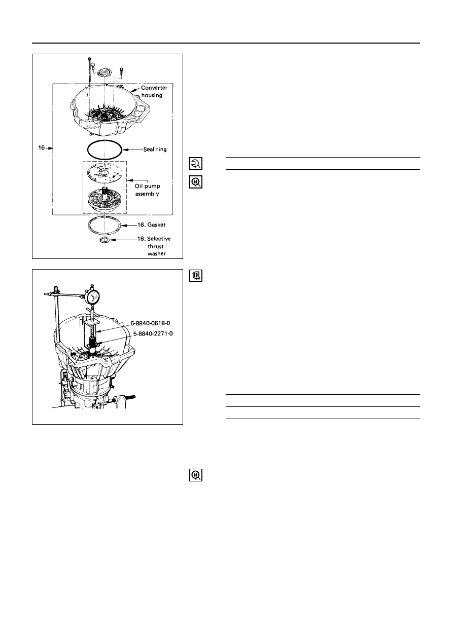
16. Converter Housing and Oil Pump Assembly
1) Install outer seal ring and gasket.
2) Install selective washer.
NOTE
Use petroleum jelly to hold selective washer in place.
3) Install complete converter housing and oil pump
assembly to adapter case.
4) Fit and tighten seven outer 13 mm screws.
Converter Housing Outer
Screw Torque
N·m (kg·m / lb·ft)
39 (4.0 / 29)
5) Ensure free rotation of pump using rotation tool.
Pump rotation tool: 5-8840-2273-0 (J-23082-01)
Overdrive end play measurement
1) Fit puller on turbine shaft.
2) Position axial play checking tool on converter
housing mating face.
3) Pull turbine shaft upwards with puller until first
resistance is met.
(Due to weight of overdrive complete assembly)
Maintain shaft in this position and set indicator to
zero.
4) Pull turbine shaft further upwards with puller.
Read end play shown on indicator.
Overdrive End Play
mm (in)
Standard
0.1 – 0.8 (0.004 – 0.031)
5) Remove axial play checking tool and puller.
NOTE:
If end play is not correct, repeat selective washer
selection.
Turbine shaft puller: 5-8840-2271-0 (J-25022) and
5-8840-0618-0 (J-24773-1)

7A1 – 174 AUTOMATIC TRANSMISSION (4L30-E)
15. Extension Housing and Flange
1) Inspect extension housing oil seal and
bearing.Replace if necessary.
Extension housing oil seal installer: 5-8840-2282-0
(J-36797)
2) Rotate transmission to horizontal position, with
valve body side down.
3) Inspect parking wheel seal ring. Replace if
necessary.
4) Install wheel parking lock assembly.
5) Install speed wheel and snap ring.
NOTE:
Use extra long nose pliers.
6) Install gasket onto extension assembly, using a
thin coating of oil.
7) Install extension housing assembly, and align
parking pawl shaft.
8) Install actuator assembly into extension
assembly.
9) Install seven 8 mm hexagon socket head screws.
Extension Housing Bolt Torque
N·m (kg·m / lb·ft)
32 (3.3 / 24)
10) Install flange and O-ring.
11) Install flange nut.
Flange Nut Torque
N·m (kg·m / lb·ft)
103 (10.5 / 76)
14. Speed Sensor
1) Inspect speed sensor O-ring. Replace if necessary.
2) Install speed sensor assembly and 10 mm screws.
Speed Sensor Bolt Torque
N·m (kg·cm / lb·in)
9 (90 / 78)
Main case end play measurement
1) Attach axial play checking tool on the extension
housing and set indicator to zero on output shaft.
2) Manually push output shaft upwards.
Main Case End Play
mm (in)
Standard
0.36 – 0.80 (0.014 – 0.031)
3) Remove axial play checking tool.
4) If end play is not correct, repeat selective washer
selection.
15.Wheel parking lock
Seal ring
15.Speed wheel
15.Retaining ring
15.Extension housing
15.Flange
15.Flange nut
14.Speed sensor
241LW001
AUTOMATIC TRANSMISSION (4L30-E) 7A1 – 175
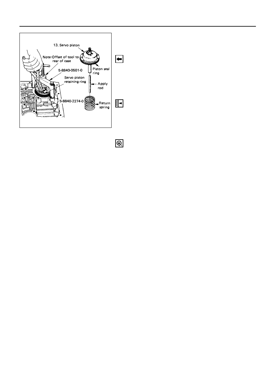
13. Servo Piston
1) Inspect piston seal ring. Replace if necessary.
2) Ensure brake band is correctly positioned. Rotate
output shaft if necessary.
3) Install servo piston fitter in servo bore.
4) Install apply rod, round end toward band, return
spring and piston assembly.
5) Install the tool with offset to rear of case.
6) Compress servo piston seal ring, using fitter while
tightening the tool screw.
7) Install servo piston retaining ring.
8) Remove tool.
9) Adjust the brake band by tightening the servo
adjusting screw to 4.5 N·m (46 kg·cm / 40 lb·in)
torque. Be certain the lock nut is loose, then back-
off the screw five turns exactly. Hold piston sleeve
with wrench and tighten lock nut to 18.5 N·m
(1.9 kg·m / 14 lb·ft) torque. Be certain the
adjusting screw does not turn.
Servo spring compressor: 5-8840-0501-0 (J-23075)
Servo piston fitter: 5-8840-2274-0 (J-38428)
Нет комментариевНе стесняйтесь поделиться с нами вашим ценным мнением.
Текст