Isuzu D-Max / Isuzu Rodeo (TFR/TFS). Manual — part 1688

6A-50 ENGINE MECHANICAL (C24SE, C22NE, 22LE, 20LE)
Valve Seating, Mill
Place cylinder head on block of wood.
Inlet and exhaust, Guide Drift and Valve Seat Cutter 5-8840-
2593-0.
Valve seat-45
°, side face, upper correction-30°, side face
(arrows on cutter).
Valve seat width:
Inlet-1.0 to 1.5 mm/0.04 to 0.06 in.
Exhaust-1.7 to 2.2 mm/0.072 to 0.088 in.
Inspection
Valve stem projection-use 5-8840-2596-0.
Important!
If dimension “A” is exceeded, use new valves.
Check valve stem projection again. If dimension “A” is
exceeded, replace cylinder head.
Cylinder Head, Overhaul
Cylinder head disassembled.
Valve, Grind
Important!
Ensure that there are no crater-like burns on the valve cone.
Regrinding possible once or twice.
Grinding of valve stem end is not permitted.
Angle at valve head-44
°
Inspection
Check valve stem projection as shown 5-8840-2596-0.
Valve, Grind in
Lubricate valve stem, use fine-graining grinding paste.
Lift up valve from seat rythmically using valve grinding tool (1)
for distribution of grinding paste.

ENGINE MECHANICAL (C24SE, C22NE, 22LE, 20LE) 6A-51
Inspection
Check contact pattern (I) on valve seat and in cylinder head.
Clean
Valves, valve guides, cylinder head.
Flywheel
Removal
1.
Remove transmission and clutch.
2.
Remove flywheel while locking with 5-88400-446-0.
Torque - Angle Method
Flywheel to crankshaft - 65 Nm/6.5 kgf
⋅m.+30° to 45°
Important!
Use new bolts.
Do not apply grease to the thread.
Installation
1.
Install clutch and transmission.
Component Parts
Flywheel and Ring gear. (Manual Transmission)

6A-52 ENGINE MECHANICAL (C24SE, C22NE, 22LE, 20LE)
Starter Ring Gear (Manual Transmission)
Removal
1.
Remove flywheel according to the corresponding
operation.
2.
Drill starter ring gear underneath tooth gap approx.
8mm/0.30in. deep with 8mm/0.25in. diameter drill.
3.
Separate starter ring gear with chisel on the drilling point.
Installation
1.
Install starter ring gear with inner chamfered edge to
flywheel.
2.
Heat starter ring gear evenly to 180
°C /356°F to 230°C
/446
°F (yellow paint mark)
3.
Install flywheel according to the corresponding operation.
Inspection
Lateral run-out of starter ring gear - max. 0.5mm/0.02in.
ENGINE MECHANICAL (C24SE, C22NE, 22LE, 20LE) 6A-53
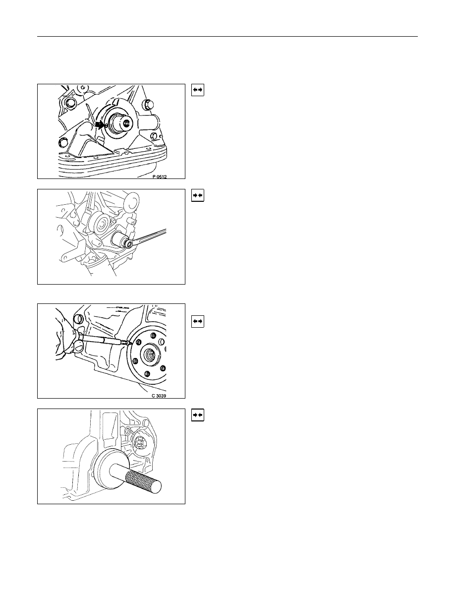
Seal Ring, Crankshaft
(Oil Pump Housing)
Removal
1.
Remove toothed belt rear cover according to the
corresponding operation.
2.
Remove sealing ring by making hole in middle of ring,
turning in self-tapping screw and edging out.
Installation
1
Install the protective sleeve to the crankshaft.
2.
Coat the sealing lip with protective grease.
3.
Install the sealing ring.
4.
Install the sealing ring using 5-8840-0455-0.
5.
Install the rear toothed belt cover and toothed belt
according to the corresponding operations.
6.
Replace the sealing ring with a new one.
7.
Tighten the belt to the crankshaft.
Seal Ring, Crankshaft Rear
Removal
1.
Remove transmission and clutch.
2.
Remove flywheel or flex plate according to the
corresponding operations.
3.
Make hole in middle of sealing ring, turn in self-tapping
screw and edge out.
Installation
1.
Install protective sleeve.
2.
Coat sealing lip with Protective Grease.
3.
Install sealing ring using 5-8840-0459-0 and 5-8840-
2597-0.
4.
Install flywheel, clutch and transmission.
Нет комментариевНе стесняйтесь поделиться с нами вашим ценным мнением.
Текст