Isuzu Rodeo UE. Manual — part 425
6E2–455
RODEO 6VD1 3.2L ENGINE DRIVEABILITY AND EMISSIONS
Installation Procedure
NOTE: Do not apply thread sealant to the sensor threads.
The sensor is coated at the factory and applying
additional sealant will affect the sensor’s ability to detect
detonation.
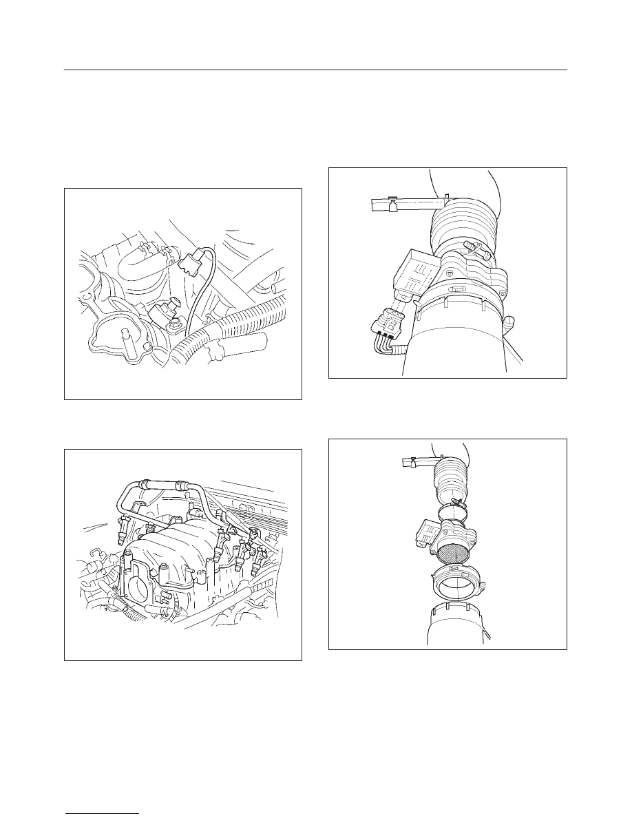
1. Screw the knock sensor into the engine block.
Tighten
f
Tighten the knock sensor to 20 N·m (177 lb in.).
014RW103
2. Connect the electrical connector to the knock sensor.
3. Install the common chamber assembly.
Refer to Common Chamber in Engine Mechanical.
014RW106
4. Install the engine cover.
5. Fill the cooling system.
Refer to Draining and Filling the Cooling System in
Engine Cooling.
6. Connect the negative battery cable.
Mass Air Flow (MAF) Sensor
Removal Procedure
1. Disconnect the negative battery cable.
2. Disconnect the electrical connector from the MAF
sensor.
TS23740
3. Loosen the clamps which secure the intake air duct
and the air cleaner to the MAF sensor.
4. Remove the intake air duct from the MAF sensor.
5. Remove the MAF sensor from the air cleaner.
TS23781
Installation Procedure
1. Install the MAF sensor on the air cleaner with the
clamp.
6E2–456
RODEO 6VD1 3.2L ENGINE DRIVEABILITY AND EMISSIONS
2. Install the intake air duct and the clamp on the MAF
sensor.
TS23781
3. Tighten the clamps to secure the MAF sensor to the
intake air duct and the air cleaner.
4. Connect the MAF electrical connector.
5. Connect the negative battery cable.
Manifold Absolute Pressure
(MAP) Sensor
Removal Procedure
1. Disconnect the negative battery cable.
2. Disconnect the electrical connector from the MAP
sensor.
055RW005
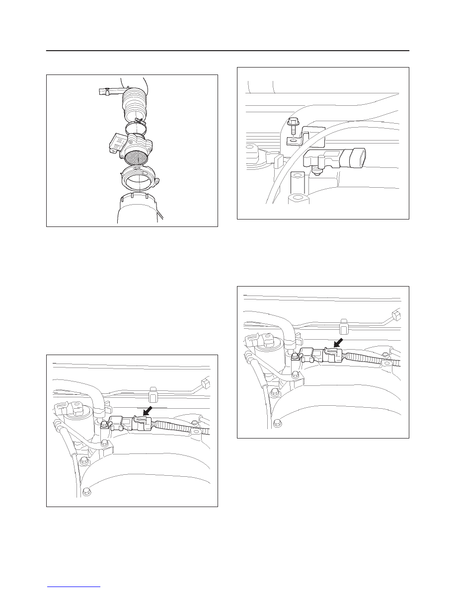
3. Remove the bolt securing the MAP sensor to the
mounting bracket on the common chamber.
4. Remove the MAP sensor from the mounting bracket.
055RW002
Installation Procedure
1. Install the MAP sensor in the mounting bracket.
2. Install the mounting bracket retaining bolt on the
common chamber.
3. Connect the MAP electrical connector.
055RW005
4. Connect the negative battery cable.
Malfunction Indicator Lamp
(MIL)
Removal and Installation Procedure
Refer to Warning light bulb, indicator light valve,
illumination light bulb, A/T indicator light bulb in Meter and
Gauge.

6E2–457
RODEO 6VD1 3.2L ENGINE DRIVEABILITY AND EMISSIONS
Powertrain Control Module
(PCM)
Service Precaution
NOTE: To prevent possible electrostatic discharge
damage to the PCM, do not touch the connector pins or
soldered components on the circuit board.
Electrostatic Discharge (ESD)
Damage
Electronic components used in the control systems are
often designed to carry very low voltage. Electronic
components are susceptible to damage caused by
electrostatic discharge. Less than 100 volts of static
electricity can cause damage to some electronic
components. By comparison, it takes as much as 4,000
volts for a person to even feel the zap of a static
discharge.
There are several ways for a person to become statically
charged. The most common methods of charging are by
friction and by induction. An example of charging by
friction is a person sliding across a car seat.
Charging by induction occurs when a person with well
insulated shoes stands near a highly charged object and
momentarily touches ground. Charges of the same
polarity are drained off leaving the person highly charged
with the opposite polarity. Static charges can cause
damage, therefore, it is important to use care when
handling and testing electronic components.
NOTE: To prevent possible Electrostatic Discharge
damage, follow these guidelines:
f
Do not touch the control module connector pins or
soldered components on the control module circuit
board.
f
Do not open the replacement part package until the
part is ready to be installed.
f
Before removing the part from the package, ground
the package to a known good ground on the vehicle.
f
If the part has been handled while sliding across the
seat, or while sitting down from a standing position, or
while walking a distance, touch a known good ground
before installing the part.
NOTE: To prevent internal PCM damage, the ignition
must be in the “OFF” position in order to disconnect or
reconnect power to the PCM (for example: battery cable,
PCM pigtail, PCM fuse, jumper cables, etc.).
IMPORTANT:
When replacing the production PCM
with a service PCM, it is important to transfer the
broadcast code and production PCM number to the
service PCM label. This will allow positive identification of
PCM parts throughout the service life of the vehicle. Do
not record this information on the metal PCM cover.
IMPORTANT:
The ignition should always be in the
“OFF” position in order to install or remove the PCM
connectors.
Service of the PCM should normally consist of either re-
placement of the PCM or EEPROM programming. If the
diagnostic procedures call for the PCM to be replaced,
the PCM should be checked first to ensure it is the correct
part. If it is, remove the faulty PCM and install the new
service PCM.
The service PCM EEPROM will not be programmed.
DTC P0601 indicates the check sum error.
Removal Procedure
1. Disconnect the negative battery cable.
2. Block the wheels.
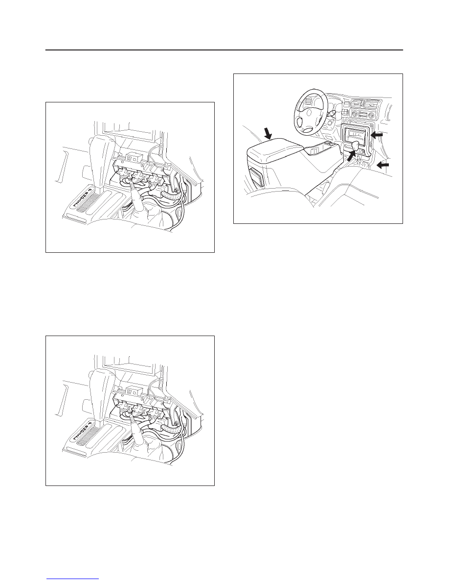
3. Remove the two screws attaching the rear console
and lift the upward rear console, then disconnect the
switch connector.
4. Remove the lower cluster assembly by pulling the
cover toward the rear.
5. Remove the transfer knob.
6. Remove the six screws attaching the upper console
and front console.
014RW128
6E2–458
RODEO 6VD1 3.2L ENGINE DRIVEABILITY AND EMISSIONS
7. Disconnect the red, white, and blue electrical
connectors at the PCM.
8. Remove the two screws in the front of the PCM.
9. Remove the one screws at the left rear of the PCM.
10. Pull the PCM straight out from the dashboard.
014RW111
Installation Procedure
1. Insert the PCM into the dashboard.
f
Line up the holes in front for the mounting screws.
2. Install the PCM with two screws in the front and one
screw at the left rear.
3. Plug the red, white, and blue connectors into the
appropriate sockets.
014RW111
4. Install the front console and lower console.
5. Install the transfer knob.
6. Connect the switch connector and install the rear
console.
014RW128
If the PCM is replaced, the new PCM will need to be
programmed.
EEPROM
General Description
The Electronically Erasable Programmable Read Only
Memory (EEPROM) is a permanent memory that is
physically soldered within the PCM. The EEPROM
contains program and calibration information that the
PCM needs to control powertrain operation.
EEPROM Programming
1. Step-up – Ensure that the following conditions have
been met:
f
The battery is fully charged.
f
The ignition is “ON.”
f
The Vehicle Interface Module cable connection at
the DLC is secure.
2. Program the PCM using the latest software matching
the vehicle. Refer to up-to-date Techline equipment
user’s instructions.
3. If the PCM fails to program, proceed as follows:
f
Ensure that all PCM connections are OK.
f
Check the Techline equipment for the latest
software version.
f
Attempt to program the PCM. If the PCM still
cannot be programmed properly, replace the PCM.
The replacement PCM must be programmed.
Functional Check
1. Perform the On-Board Diagnostic System Check.
2. Start the engine and run for one minute.
3. Scan for DTCs using the Tech 2.
Нет комментариевНе стесняйтесь поделиться с нами вашим ценным мнением.
Текст