Isuzu Rodeo UE. Manual — part 566
8D–112
WIRING SYSTEM
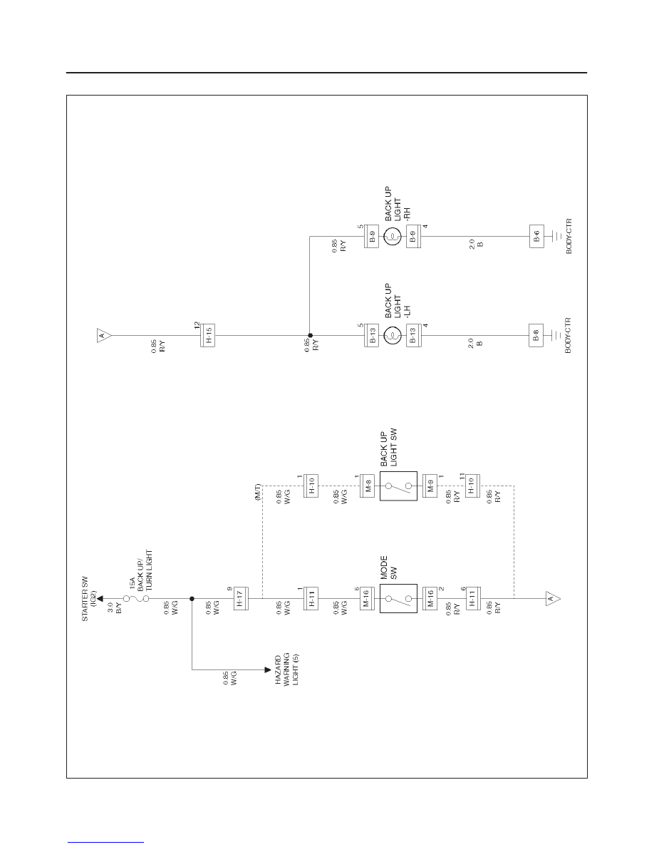
Circuit Diagram
D08RW036
8D–113
WIRING SYSTEM
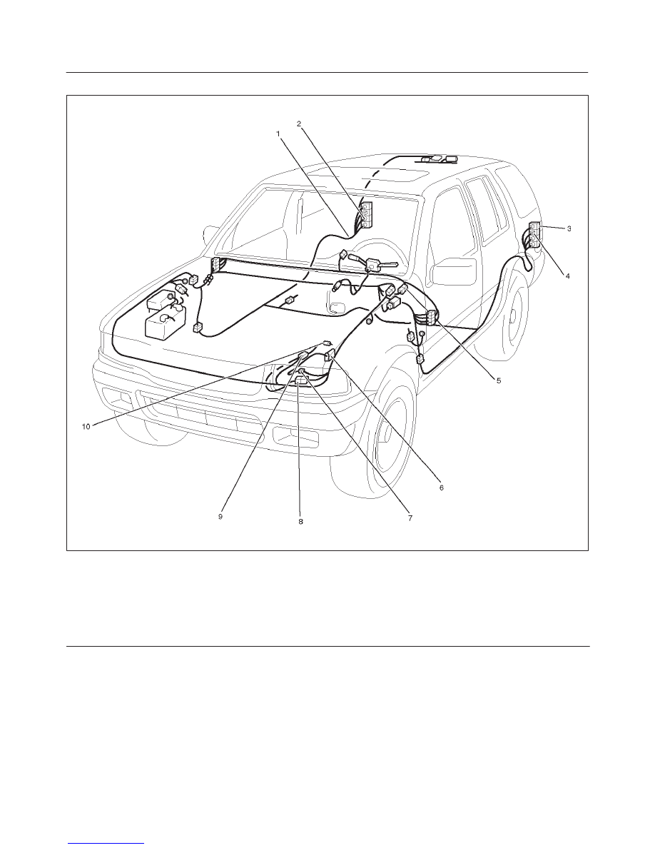
Parts Location
D08RW112
Legend
(1) B–9
(2) Backup Light – RH
(3) Backup Light – LH
(4) B–13
(5) H–1, H–17
(6) Mode SW
(7) M–16
(8) H–10, H–11
(9) M–8, M–9
(10) Backup Light SW
8D–114
WIRING SYSTEM
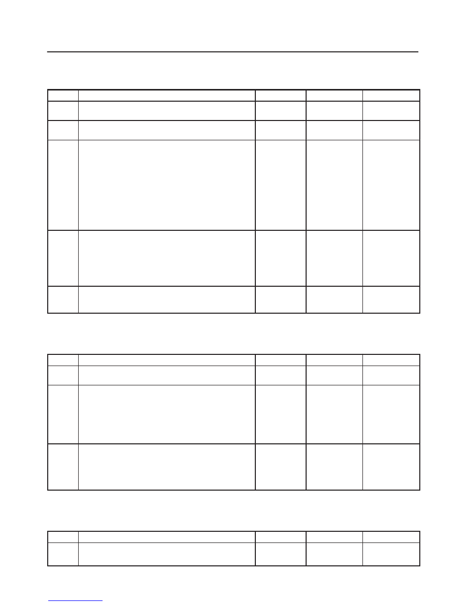
Diagnosis
Both Backup Lights Inoperative
Step
Action
Value(s)
Yes
No
1
Is fuse 14 (15A) normal?
—
Go to Step 2
Replace the
fuse
2
Is B-8 terminal ground securely?
—
Go to Step 3
Replace the
securely
3
Turn the starter sw on.
Is the battery voltage applied between the move sw (or
backup light sw) harness side connector M-16 terminal
5 (M-8 terminal 1) and the ground?
—
Go to Step 4
Repair poor
connection at
connectors or
an open
circuit
between the
fuse 6 (15A)
and M-16
terminal 5 or
(M-8 terminal
1)
4
1. Set the transmission gear to the reverse position.
2. Disconnect the mode sw (or backup light sw)
connector.
Is there continuity between switch side connectors
M-16 terminal 2 and 5 (M-5 terminal 1 and M-9 terminal
1)
—
Go to Step 5
Replace the
stoplight sw
5
Repair a poor connection at the connectors or an open
circuit between M-16 terminal 2 (M-9 terminal 1) and
H-15 terminal 12)
—
—
Replace the
stoplight sw
NOTE: Connectors inparenthesis “( )” indicates the
model with manual transmission.
Backup Light On The Left (or Right) Side Inoperative
Step
Action
Value(s)
Yes
No
1
Is the backup light bulb on the lift (or right) side normal?
—
Go to Step 2
Replace the
bulb
2
Is there any continuity between the backup light
harness side connectors B-13 terminal 5 (B-9 terminal
5) and H-15 terminal 12?
—
Go to Step 3
Replace a
poor
connection at
connectors or
an open
circuit in the
circuit
3
Repair a poor connection at connectors or an open
circuit between backup light harness side connector
B-13 terminal 4 (B-9 terminal 4) and B-8 terminal (B-6
terminal )
Is the action complete?
—
Verify repair
—
NOTE: Connectors inparenthesis “( )” indicates the
model with manual transmission.
Backup Lights Remain On
Step
Action
Value(s)
Yes
No
1
Repair or replace the mode sw (backup light sw)
Is the action complete?
—
Verify repair
—
8D–115
WIRING SYSTEM
Horn
General Description
The circuit consists of horn (high note), horn (low note),
horn relay and horn switch.
When horn switch is pushed, (independent of position of
starter switch) horn relay is activated to sound horns.
Нет комментариевНе стесняйтесь поделиться с нами вашим ценным мнением.
Текст