Isuzu Rodeo UE. Manual — part 565
8D–108
WIRING SYSTEM
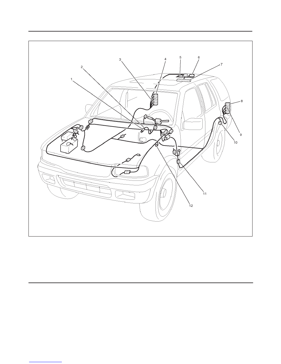
Parts Location
D08RW111
Legend
(1) Stop light SW
(2) I–18
(3) B–9
(4) Stop light – RH
(5) H–21
(6) G–10, G–11
(7) High Mounted Stop Light
(8) Stop light – LH
(9) B–13
(10) H–23
(11) H–32
(12) B–6, B–8
8D–109
WIRING SYSTEM
Diagnosis
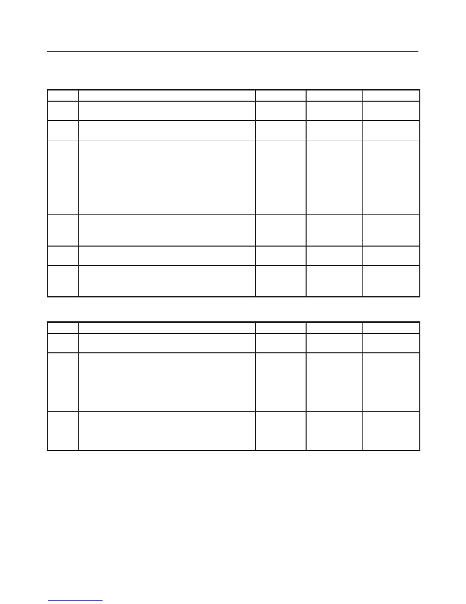
Both Stoplights Inoperative
Step
Action
Value(s)
Yes
No
1
Is fuse 6 (15A) normal?
—
Go to Step 2
Replace the
fuse
2
Is B-8 terminal ground securely?
—
Go to Step 3
Replace the
securely
3
Is the battery voltage applied I-18 terminal 1 of the
stoplight sw?
—
Go to Step 4
Repair poor
connection at
connectors or
an open
circuit
between the
fuse 6 (15A)
and I-18
terminal 1
4
Remove the stoplight sw.
Is there continuity between I-18 terminal 1 and 4 of the
switch when push rod is out?
—
Go to Step 5
Replace the
stoplight sw
5
Does the push rod of the stoplight sw operate
smoothly?
—
Go to Step 6
Replace the
stoplight sw
6
Repair a poor connection of connectors or an open
circuit between I-18 terminal 4 and H-32 terminal 7.
Is the action complete?
—
Verify repair
—
Stoplight On The Left (or Right) Side Inoperative
Step
Action
Value(s)
Yes
No
1
Is the stoplight bulb on the left (or right) side normal?
—
Go to Step 2
Replace the
bulb
2
Is there any continuity between the stoplight connector
B-13 terminal 3 (B-9 terminal 3) and H-32 terminal7?
—
Go to Step 3
Replace a
poor
connection at
connectors or
an open
circuit in the
circuit
3
Repair a poor connection at connectors or an open
circuit between B-13 terminal 4 (B-9 terminal 4) and B-8
terminal (B-6 terminal )?
Is the action complete?
—
Verify repair
8D–110
WIRING SYSTEM
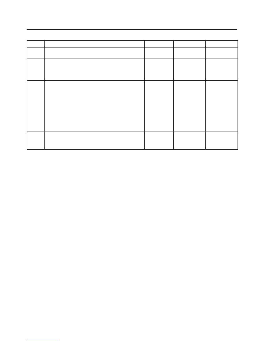
High Mounted Stoplight Inoperative
Step
Action
Value(s)
Yes
No
1
Is B-9 terminal ground securely?
—
Go to Step 2
Ground it
securely
2
Remove the high mount stoplight.
Is there any continuity between the high mount
stoplight connector G-11 terminal 1 and G-10 terminal
1?
—
Go to Step 3
Repair or
replace the
high mount
stoplight
3
Is the battery voltage applied between G-11 terminal 1
and the ground when the brake pedal is depressed?
—
Go to Step 4
Repair a
poor
connection at
the
connectors or
an open
circuit
between G-11
terminal 1
and H-21
terminal 1
4
Repair a poor connection at the connectors or an open
circuit between G-10 terminal 1 and B-6 terminal.
Is the action complete?
—
Verify repair
—
8D–111
WIRING SYSTEM
Backup Light
General Description
The circuit consists of backup light switch (M/T), mode
switch (A/T) and backup light.
When shift lever is set to “R” position, backup light switch
(M/T) or mode switch (A/T) is activated to illuminate
backup light.
Нет комментариевНе стесняйтесь поделиться с нами вашим ценным мнением.
Текст