Isuzu Rodeo UE. Manual — part 23
1A–62 HEATING, VENTILATION AND AIR CONDITIONING (HVAC)
Removal
1. Disconnect the battery ground cable.
2. Discharge and recover refrigerant.
D
Refer to Refrigerant Recovery in this section.
3. Remove radiator grille.
4. Remove clip and clamp.
5. Disconnect liquid line (High-pressure pipe).
6. Disconnect suction line (Low-pressure pipe) using a
back-up wrench.
7. Disconnect suction line (Low-pressure hose) using a
back-up wrench.
8. Disconnect discharge line (High-pressure hose)
using a back-up wrench.
D
Use a backup wrench when disconnecting and
reconnecting the refrigerant lines.
D
When removing the refrigerant line connecting part,
the connecting part should immediately be plugged
or capped to prevent foreign matter from being
mixed into the line.
Installation
To install, follow the removal steps in the reverse order,
noting the following point:
1. O-rings cannot be reused. Always replace with new
ones.
2. Be sure to apply new compressor oil to the O-rings
when connecting lines.
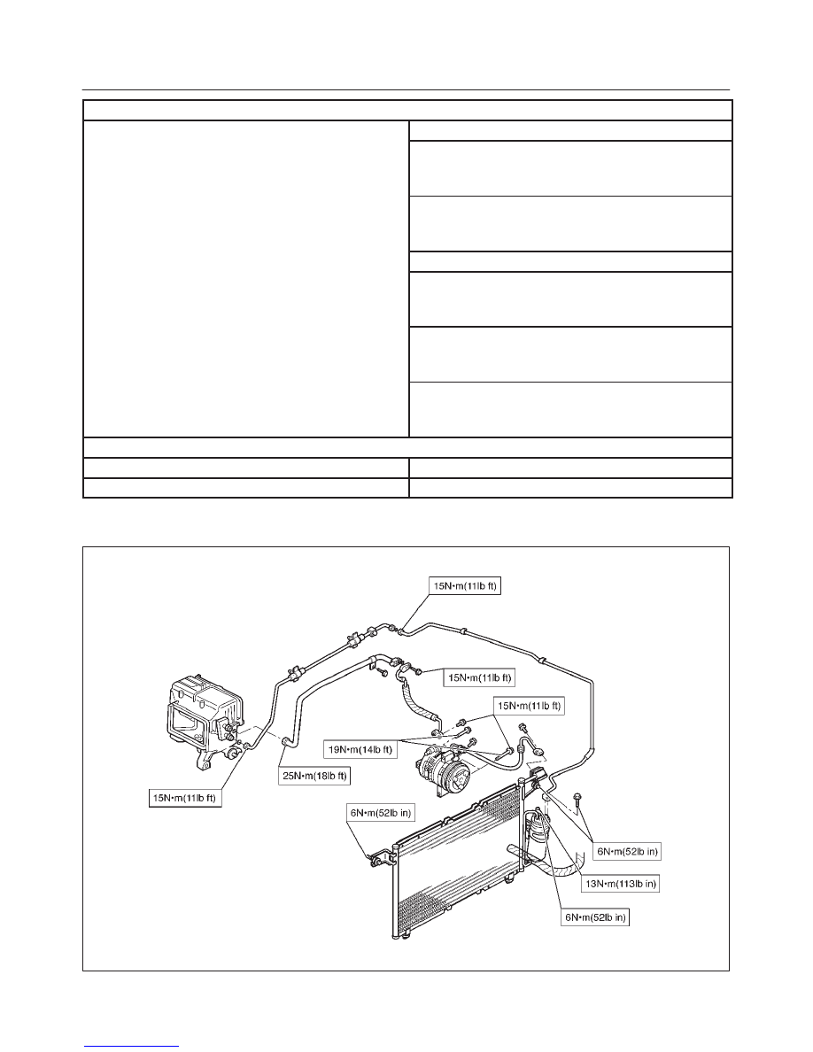
3. Tighten the refrigerant line to the specified torque.
Refer to Main Data and Specifications for Torque
Specifications in this section.
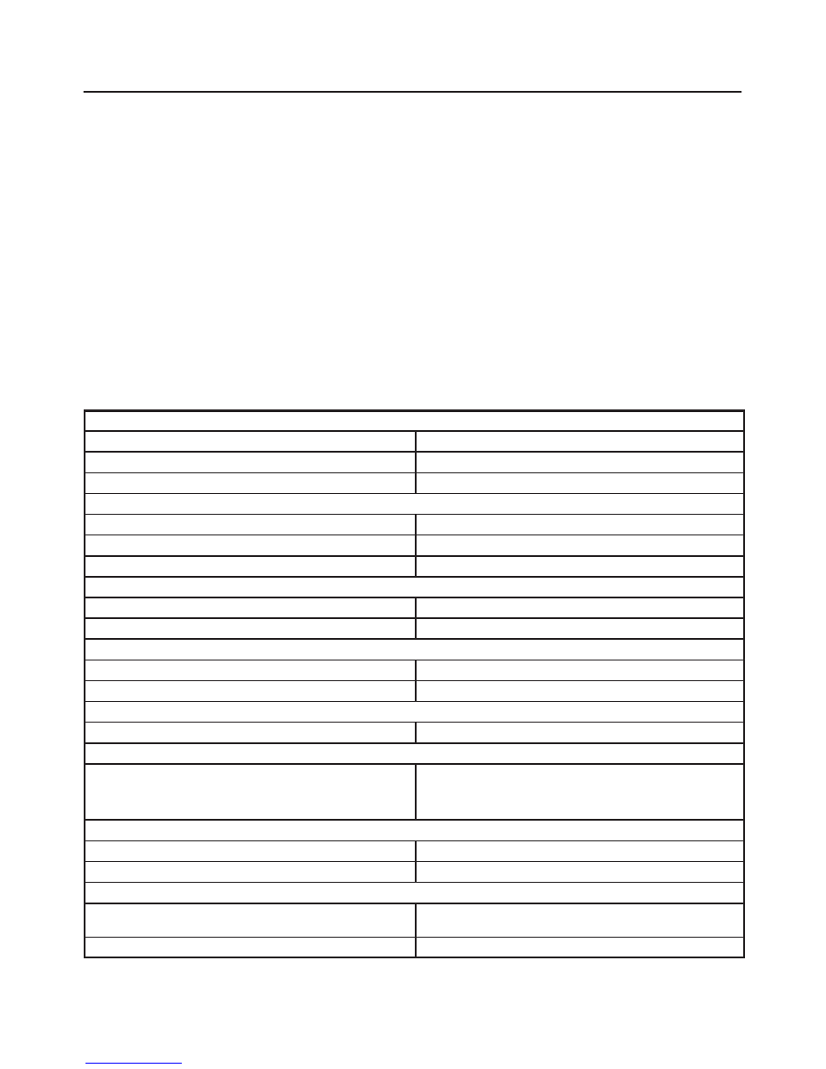
Main Data And Specifications
General Specifications
Heater Unit
Temperature control
Reheat air mix system
Capacity
3,700 Kcal./hr.
Air flow
280 m
#
/h
HEATER CORE
Type
Fin and tube type
Element dimension
167 mm (6.6 in.)
×
151 mm (5.9 in.)
×
35 mm (1.4 in.)
Radiating area
Approx. 2.4 m
@
EVAPORATOR ASSEMBLY
Capacity
4,100 Kcal./hr.
Air flow
430 m
#
/hr
EVAPORATOR CORE
Type
Al-laminate louver fin type
Element dimension
235 mm (9.3 in.)
×
224 mm (8.8 in.)
×
60 mm (2.4 in.)
EXPANSION VALVE
Type
External pressure equalizer type
THERMOSTAT SWITCH
Type
Electronic thermostat
OFF: Below 0.5
±
0.5
°
C (32.9
±
0.9
°
F)
ON: Above 4.5
±
0.5
°
C (40.1
±
0.9
°
F)
CONDENSER
Type
Parallel flow type
Radiation performance
9,400 Kcal./hr
RECEIVER/DRIER
Type
Assembly includes sight glass with dual (triple) pres-
sure switch (V6) or pressure sensor (L14)
Internal volume
300 cc (10 fl.oz.)
HEATING, VENTILATION AND AIR CONDITIONING (HVAC) 1A–63
PRESSURE SWITCH
Type
Dual pressure switch
Low pressure control
ON: 205.9
±
29.4 kPa (29.9
±
4.3 psi)
OFF: 176.5
±
24.5 kPa (25.6
±
3.6 psi)
High pressure control
ON: 2353.6
±
196.1 kPa (341.3
±
28.4 psi)
OFF: 2942.0
±
196.1 kPa (426.6
±
28.4 psi)
Triple pressure switch (V6, A/T)
Low pressure control
ON: 196.3
±
29.4 kPa (27.0
±
4.3 psi)
OFF: 176.5
±
19.6 kPa (25.6
±
2.8 psi)
Medium pressure control
ON: 1471.0
±
98.1 kPa (213.3
±
14.2 psi)
OFF: 1078.7
±
117.7 kPa (156.4
±
17.7 psi)
High pressure control
ON: 2353.6
±
196.1 kPa (341.3
±
28.4 psi)
OFF: 2942.0
±
196.1 kPa (426.6
±
28.4 psi)
REFRIGERANT
Type
HFC-134a
Specified amount
650 g (1.43 lbs.)
Torque Specifications
852RX003
1A–64 HEATING, VENTILATION AND AIR CONDITIONING (HVAC)
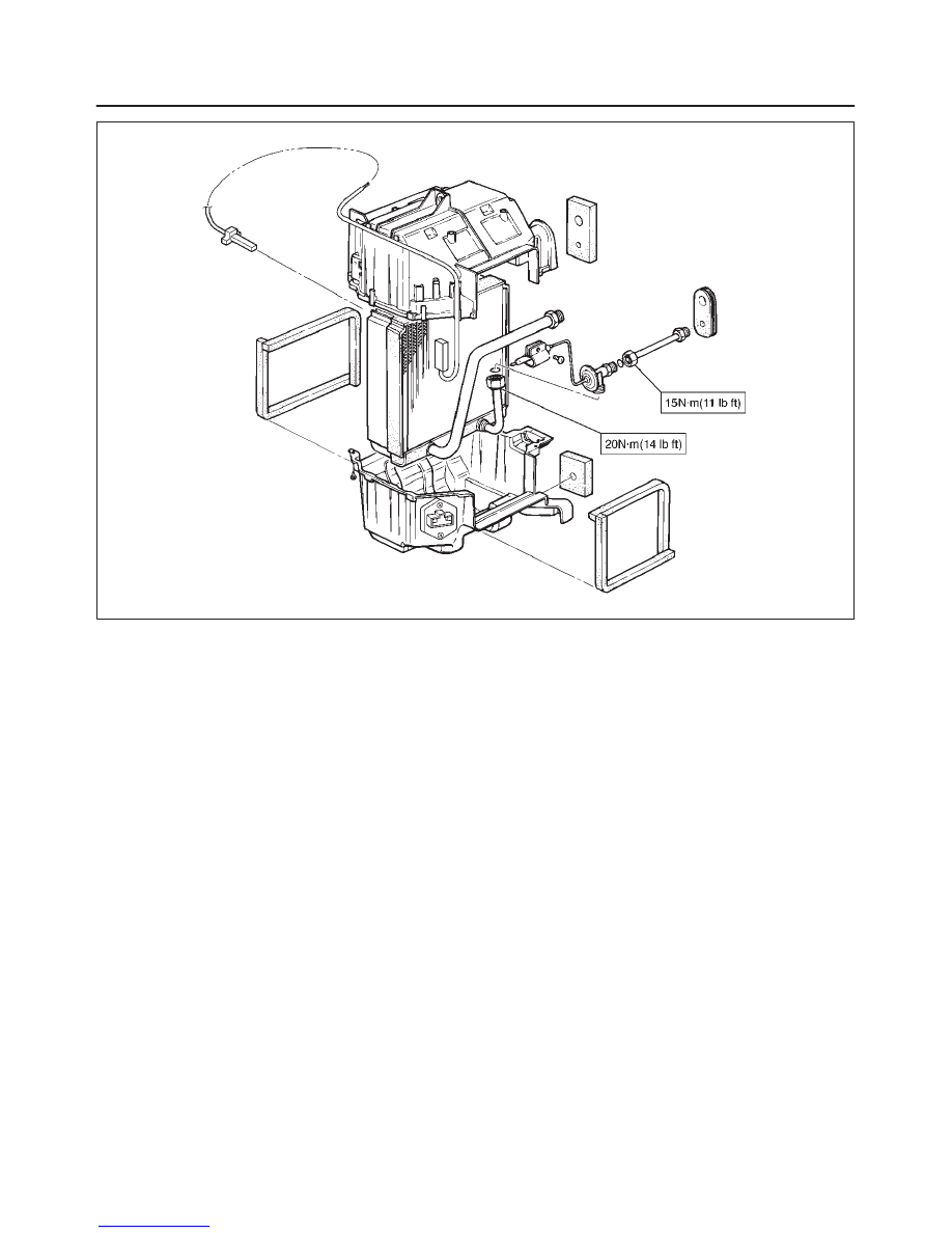
874RX006
HEATING, VENTILATION AND AIR CONDITIONING (HVAC) 1A–65
Compressor
Service Precaution
WARNING: THIS VEHICLE HAS A SUPPLEMENTAL
RESTRAINT SYSTEM (SRS). REFER TO THE SRS
COMPONENT LOCATION VIEW IN ORDER TO
DETERMINE WHETHER YOU ARE PERFORMING
SERVICE ON OR NEAR THE SRS COMPONENTS OR
THE SRS WIRING. WHEN YOU ARE PERFORMING
SERVICE ON OR NEAR THE SRS COMPONENTS OR
THE SRS WIRING, REFER TO THE SRS ON-VEHICLE
SERVICE INFORMATION. FAILURE TO FOLLOW
CAUTIONS COULD RESULT IN POSSIBLE AIR BAG
DEPLOYMENT, PERSONAL INJURY, OR
OTHERWISE UNNEEDED SRS SYSTEM REPAIRS.
CAUTION: Always use the correct fastener in the
proper location. When you replace a fastener, use
ONLY the exact part number for that application.
ISUZU will call out those fasteners that require a
replacement after removal. ISUZU will also call out
the fasteners that require thread lockers or thread
sealant. UNLESS OTHERWISE SPECIFIED, do not
use supplemental coatings (paints, greases, or other
corrosion inhibitors) on threaded fasteners or
fastener joint interfaces. Generally, such coatings
adversely affect the fastener torque and the joint
clamping force, and may damage the fastener. When
you install fasteners, use the correct tightening
sequence and specifications. Following these
instructions can help you avoid damage to parts and
systems.
General Description
When servicing the compressor, keep dirt or foreign
material from getting on or into the compressor parts and
system. Clean tools and a clean work area are important
for proper service. The compressor connections and the
outside of the compressor should be cleaned before any
”On–Vehicle” repair, or before removal of the
compressor. The parts must be kept clean at all times and
any parts to be reassembled should be cleaned with
Trichloroethane, naphtha, kerosene, or equivalent
solvent, and dried with dry air. Use only lint free cloths to
wipe parts.
The operations described below are based on bench
overhaul with compressor removed from the vehicle,
except as noted. They have been prepared in order of
accessibility of the components. When the compressor is
removed from the vehicle for servicing, the oil remaining
in the compressor should be discarded and new
compressor oil added to the compressor.
Compressor malfunction will appear in one of four ways:
noise, seizure, leakage or low discharge pressure.
Resonant compressor noises are not cause for alarm;
however, irregular noise or rattles may indicate broken
parts or excessive clearances due to wear. To check
seizure, de–energize the magnetic clutch and check to
see if the drive plate can be rotated. If rotation is
impossible, the compressor is seized. Low discharge
pressure may be due to a faulty internal seal of the
compressor, or a restriction in the compressor. Low
discharge pressure may also be due to an insufficient
refrigerant charge or a restriction elsewhere in the
system. These possibilities should be checked prior to
servicing the compressor. If the compressor is
inoperative, but is not seized, check to see if current is
being supplied to the magnetic clutch coil terminals.
The compressor oil used in the HFC–134a system
compressor differs from that used in R–12 systems.
Also, compressor oil to be used varies according to the
compressor model. Be sure to avoid mixing two or more
different types of oil.
If the wrong oil is used, lubrication will be poor and the
compressor will seize or malfunction.
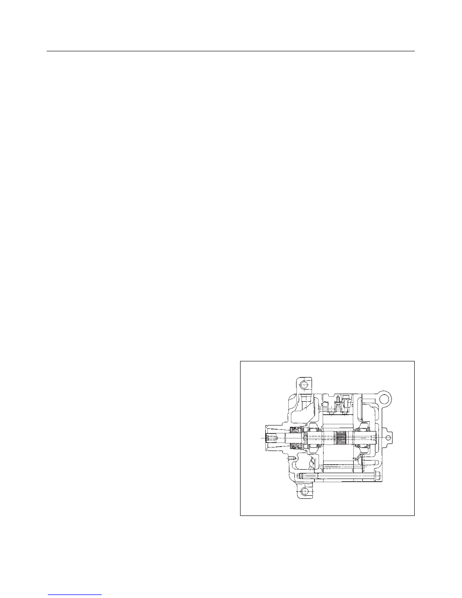
DKV-14G Type Compressor
DKV–14G is equipped with five–vane rotary compressor.
These vanes are built into a rotor which is mounted on a
shaft.
When the shaft rotates, the vanes built into the cylinder
block assembly are operated by centrifugal force.
This changes the volume of the spare formed by the rotor
and cylinder, resulting in the intake and compression of
the refrigerant gas. The discharge valve and the valve
stopper, which protects the discharge valve, are built into
the cylinder block assembly. There is no suction valve but
a shaft seal is installed between the shaft and head; a
trigger valve, which applies back pressure to the vanes, is
installed in the cylinder block and a refrigerant gas
temperature sensor is installed in the front head.
The specified quantity of compressor oil is contained in
the compressor to lubricate the various parts using the
refrigerant gas discharge pressure.
871RX002
Нет комментариевНе стесняйтесь поделиться с нами вашим ценным мнением.
Текст