Isuzu Rodeo UE. Manual — part 24
1A–66 HEATING, VENTILATION AND AIR CONDITIONING (HVAC)
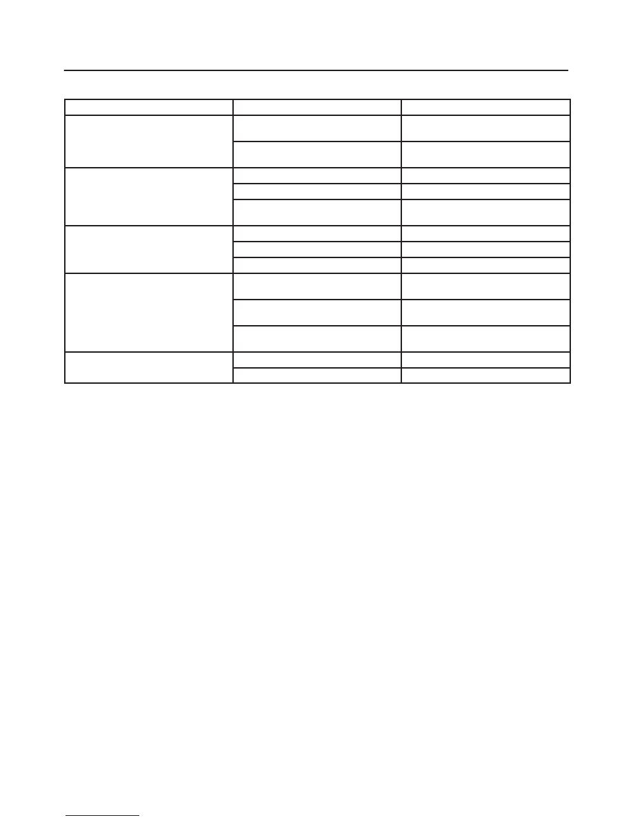
Diagnosis
Condition
Possible cause
Correction
Noise from compression
Defective rotor/piston
Replace compressor/cylinder and
shaft assembly
Defective shaft
Replace compressor/cylinder and
shaft assembly
Noise from magnetic clutch
Defective bearing
Replace magnetic clutch
Defective clutch
Replace magnetic clutch
Clearance between drive plate and
pulley not standard
Adjust the clearance or replace
magnetic clutch
Insufficient cooling
Defective gasket
Replace compressor/gasket
Defective rotor/reed valve
Replace compressor/valve plate
Defective trigger valve/suction valve
Replace compressor/suction valve
Not rotating
Defective rotor/piston
Replace compressor/cylinder and
shaft assembly
Defective shaft
Replace compressor/cylinder and
shaft assembly
Rotating parts seized due to
insufficient oil
Replace compressor
Oil and/or gas leakage
Defective seal
Replace compressor/shaft seal
Defective O-ring
Replace
HEATING, VENTILATION AND AIR CONDITIONING (HVAC) 1A–67
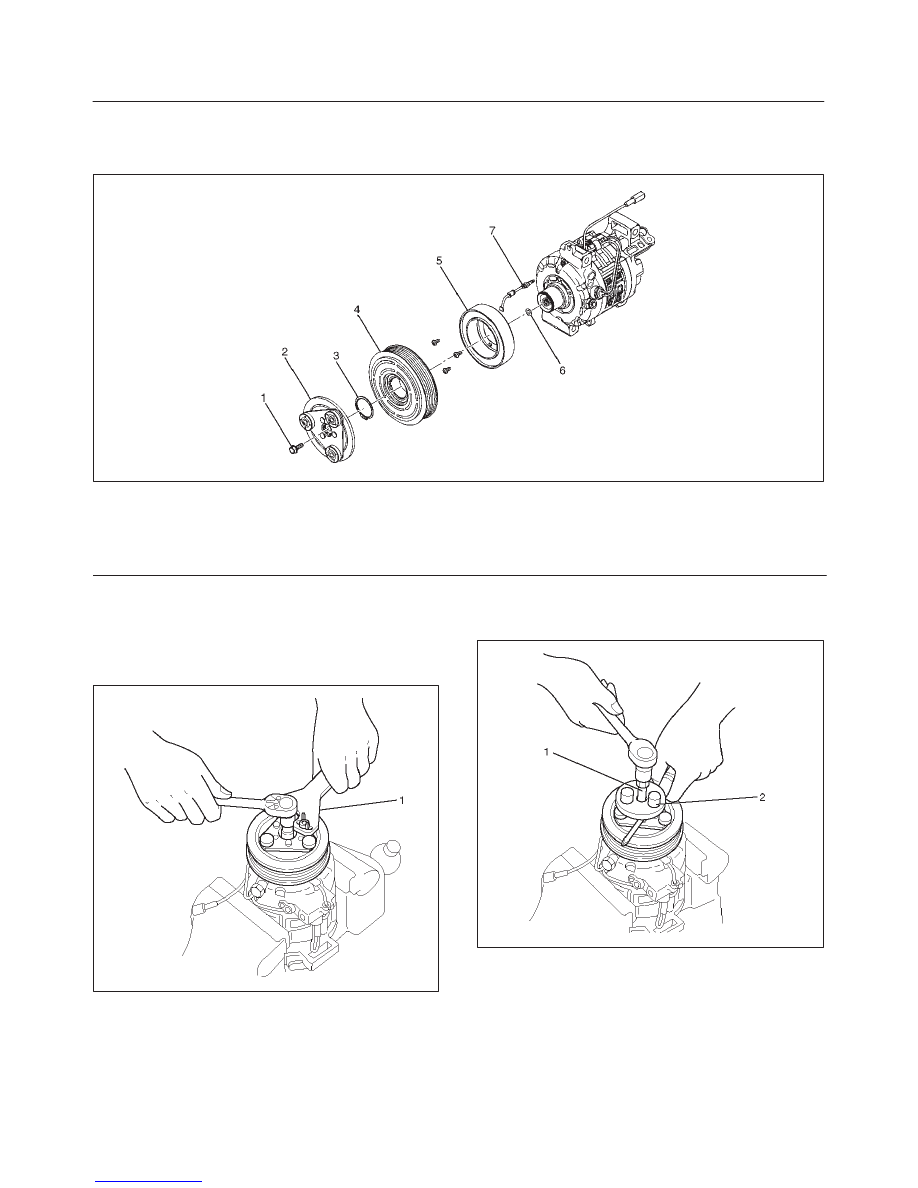
Magnetic Clutch Assembly (DKV-14D Type)
Parts Location View
871RW009
Legend
(1) Drive Plate bolt
(2) Drive Plate
(3) Snap Ring
(4) Pulley Assembly
(5) Field Coil
(6) Shim (s)
(7) Lead Wire
Removal
1. Using drive plate holder J-33939 (1) to prevent the
drive plate from rotating, then remove the drive plate
bolt.
871RW014
2. Remove drive plate by using drive plate puller
J-33944-A (2) and forcing screw J-33944-4 (1).
871RW013
1A–68 HEATING, VENTILATION AND AIR CONDITIONING (HVAC)
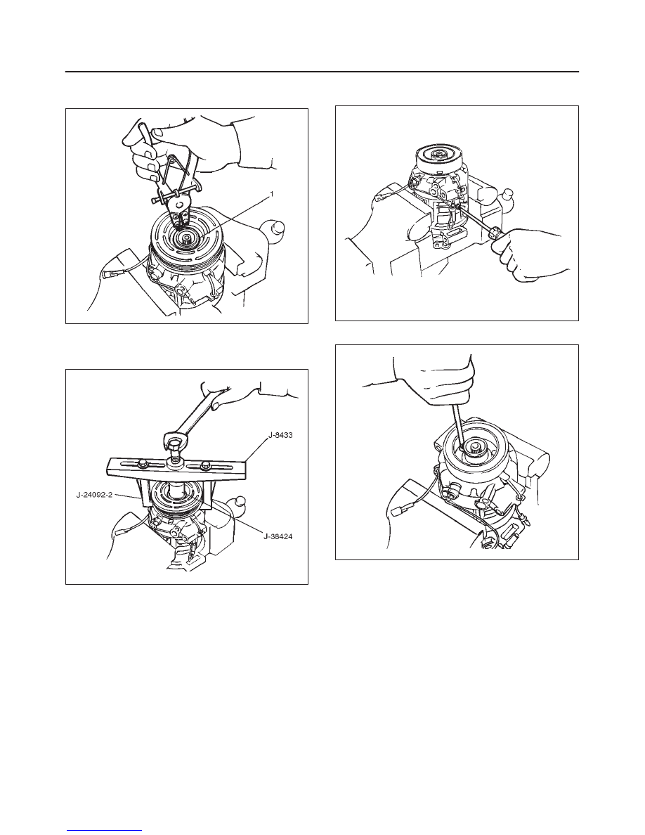
3. Remove shim (s).
4. Remove snap ring (1) by using snap ring pliers.
871RW016
5. Remove pulley assembly by using pulley puller pilot
J-38424, pulley puller J-8433 and pulley puller leg
J-24092-2.
871RS009
6. Loosen screw and disconnect the coil lead wire
connector.
871RS010
7. Loosen three screws and remove the field coil.
871RS011
Inspection and Repair
Drive Plate
If the frictional surface shows signs of damage due to
excessive heat, the drive plate and pulley should be
replaced.
Pulley Assembly
Check the appearance of the pulley assembly. If the
frictional surface of the pulley shows signs of excessive
grooving due to slippage, both the pulley and drive plate
should be replaced. The frictional surfaces of the pulley
assembly should be cleaned with a suitable solvent
before reinstallation.
Coil
Check coil for loose connector or cracked insulation.
HEATING, VENTILATION AND AIR CONDITIONING (HVAC) 1A–69
Installation
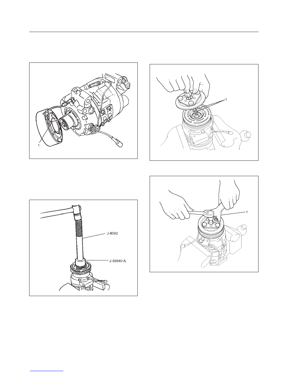
1. Install field coil.
f
Align the located portion (1) of the field coil and
compressor.
871RW017
f
Tighten the mounting screw to the specified torque.
Torque: 5N·m (44 lb in)
2. Connect the lead wire connector with the rubber hold
and tighten the screw.
3. Install pulley assembly by using pulley installer
J-33940-A and drive handle J-8092.
871RS013
4. Install snap ring.
5. Install shim (s).
6. Install the drive plate to the compressor drive shaft
together with the original shim(s)(1). Press the drive
plate by hand.
871RW012
7. Install drive plate bolt by using drive plate holder
J-33939 (1) to prevent the drive plate from rotating.
871RW014
f
Tighten the drive plate bolt to the specified torque.
Torque: 13 N·m (113 lb in)
f
After tightening the drive plate bolt, check to be sure
the pulley rotates smoothly.
Нет комментариевНе стесняйтесь поделиться с нами вашим ценным мнением.
Текст