Isuzu Rodeo UE. Manual — part 380
6E2–275
RODEO 6VD1 3.2L ENGINE DRIVEABILITY AND EMISSIONS
Diagnostic Trouble Code (DTC) P0337 CKP Sensor Circuit Low Frequency
D06RX017
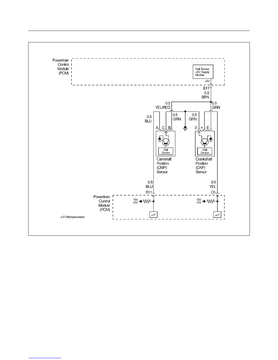
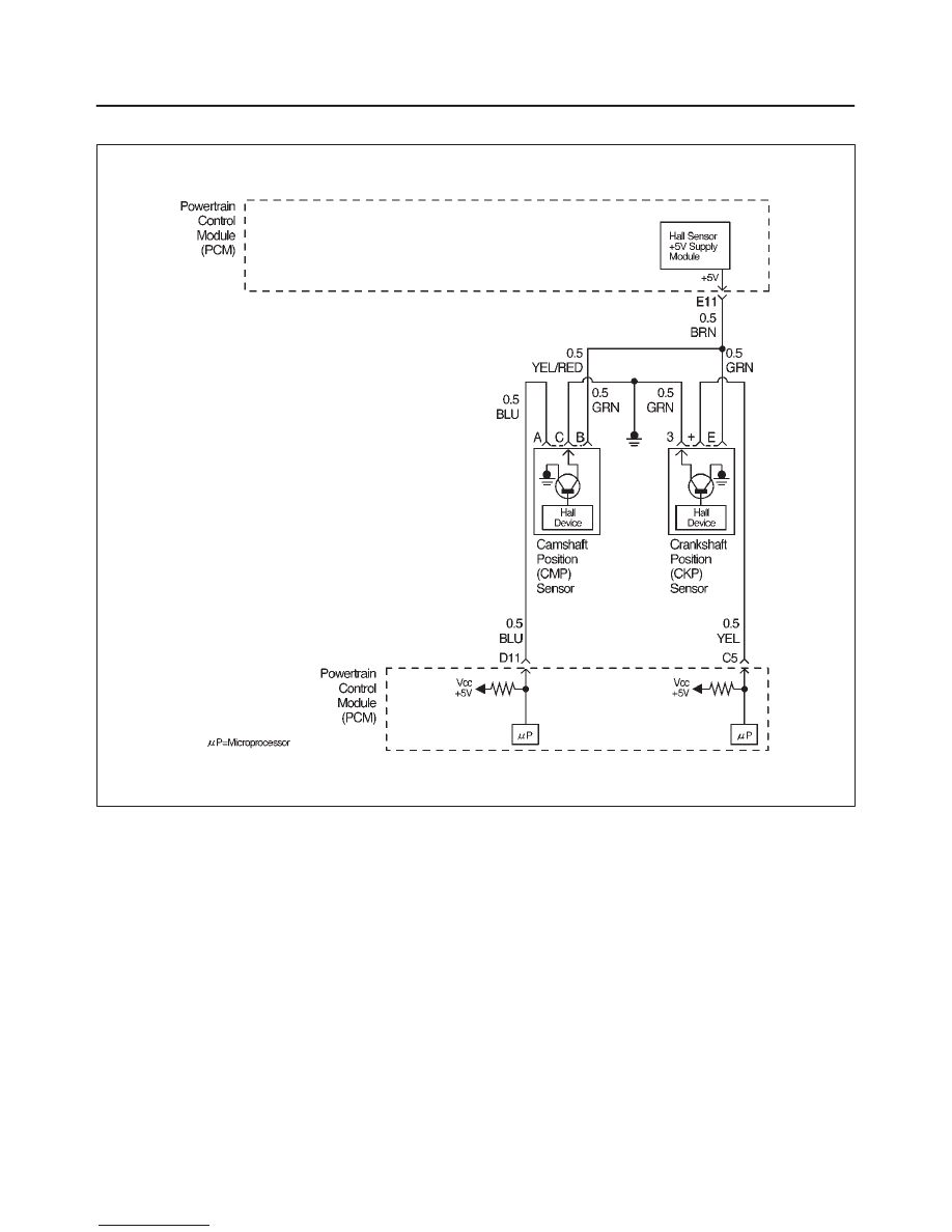
Circuit Description
The 58X reference signal is produced by the crankshaft
position (CKP) sensor. During one crankshaft revolution,
58 crankshaft reference pulses will be produced. The
powertrain control module (PCM) uses the 58X reference
signal to calculate engine RPM and crankshaft position.
The PCM constantly monitors the number of pulses on
the 58X reference circuit and compares them to the
number of camshaft position (CMP) signal pulses being
received. If the PCM does not receive pulses on the 58X
reference circuit, DTC P0337 will set.
Conditions for Setting the DTC
f
No camshaft position (CMP) sensor DTCs are set.
f
Engine cranking.
f
Crankshaft position (CKP) sensor signal is not present
between two cam pulses.
f
CKP reference pulse is not detected within 8 CMP
pulses.
Action Taken When the DTC Sets
f
The PCM will illuminate the malfunction indicator lamp
(MIL) after the second consecutive trip in which the
fault is detected.
f
The PCM will store conditions which were present
when the DTC was set as Freeze Frame and in the
Failure Records data.
Conditions for Clearing the MIL/DTC
f
The PCM will turn the MIL “OFF” on the third
consecutive trip cycle during which the diagnostic has
been run and the fault condition is no longer present.
f
A history DTC P0337 will clear after 40 consecutive
warm-up cycles have occurred without a fault.

6E2–276
RODEO 6VD1 3.2L ENGINE DRIVEABILITY AND EMISSIONS
f
DTC P0337 can be cleared by using the Tech 2 “Clear
Info” function or by disconnecting the PCM battery
feed.
Diagnostic Aids
An intermittent may be caused by a poor connection,
rubbed-through wire insulation or a wire broken inside the
insulation. Check for:
f
Poor connection – Inspect the PCM harness and
connectors for improper mating, broken locks,
improperly formed or damaged terminals, and poor
terminal-to-wire connection.
f
Damaged harness – Inspect the wiring harness for
damage. If the harness appears to be OK, disconnect
the PCM, turn the ignition on and observe a voltmeter
connected to the 58X reference circuit at the PCM
harness connector while moving connectors and
wiring harnesses related to the ICM. A change in
voltage will indicate the location of the fault.
Reviewing the Failure Records vehicle mileage since the
diagnostic test last failed may help determine how often
the condition that caused the DTC to be set occurs. This
may assist in diagnosing the condition.
DTC P0337 – CKP Sensor Circuit Low Frequency
Step
Action
Value(s)
Yes
No
1
Was the “On-Board Diagnostic (OBD) System Check”
performed?
—
Go to
Step 2
Go to
OBD
System
Check
2
Attempt to start the engine.
Does the engine start?
—
Go to
Step 3
Go to
Chart 3
3
1. Review and record Failure Records information.
2. Clear DTC P0337.
3. Start the engine and idle for 1 minute.
4. Observe DTCs.
Is DTC P0337 set?
—
Go to
Step 4
Refer to
Diagnostic
Aid
4
1. Disconnect the CKP sensor.
2. Ignition “ON.”
3. Using a DVM, verify that 5 V reference and ground
are being supplied at the sensor connector (PCM
side).
Are 4-6 volts and ground available at the sensor?
—
Go to
Step 7
Go to
Step 5
5
1. Ignition “ON.”
2. With a DVM, backprobe the PCM connector 5 V
reference and ground connections.
Are 5 V reference and ground available at the PCM?
—
Go to
Step 6
Go to
Step 11
6
Check 5 V reference or ground between the CKP
sensor and PCM and repair the open circuit, short to
ground or short to voltage.
Is the action complete?
—
Verify repair
—
7
1. Ignition “OFF.”
2. Disconnect the PCM and CKP sensor.
3. Check for an open or a short to ground in the 58X
reference circuit between the CKP sensor
connector and the PCM harness connector.
4. If a problem is found, repair as necessary.
Was a problem found?
—
Verify repair
Go to
Step 8
8
1. Reconnect the PCM and CKP sensor.
2. Connect a DVM to measure voltage on the 58X
reference circuit at the PCM connector.
3. Observe the voltage while cranking the engine.
Is the voltage near the specified value?
2.5 V
Go to
Step 11
Go to
Step 9

6E2–277
RODEO 6VD1 3.2L ENGINE DRIVEABILITY AND EMISSIONS
DTC P0337 – CKP Sensor Circuit Low Frequency
(Cont'd)
Step
No
Yes
Value(s)
Action
9
Check the connections at the CKP sensor and replace
the terminals if necessary.
Did any terminals require replacement?
—
Verify repair
Go to
Step 10
10
Replace the CKP sensor. Use caution and avoid hot oil
that may drip out.
Is the action complete?
—
Verify repair
—
11
Check the connections at the PCM and replace the
terminals if necessary.
Did any terminals require replacement?
—
Verify repair
Go to
Step 12
12
Replace the PCM.
IMPORTANT: The replacement PCM must be
programmed. Refer to
On-Vehicle Service in
Powertrain Control Module and Sensors for
procedures.
And also refer to latest service bulletin.
Check to see if the Latest software is released or not.
And then Down Load the LATEST PROGRAMMED
SOFTWARE to the replacement PCM.
Is the action complete?
—
Verify repair
—
6E2–278
RODEO 6VD1 3.2L ENGINE DRIVEABILITY AND EMISSIONS
Diagnostic Trouble Code (DTC) P0341 CMP Sensor Circuit Performamce
D06RX017
Circuit Description
The CMP signal is produced by the camshaft position
(CMP) sensor pulses when the engine is running and
crankshaft position (CKP) sync pulses are also being
received. The powertrain control module (PCM) uses the
CMP signal pulses to initiate sequential fuel injection.
The PCM constantly monitors the number of pulses on
the CMP signal circuit and compares the number of CMP
pulses to the number of 58X reference pulses received. If
the PCM receives an incorrect number of pulses on the
CMP reference circuit, DTC P0341 will set and the PCM
will initiate injector sequence without the CMP signal with
a one in six chance that injector sequence is correct. The
engine will continue to start and run normally, although
the misfire diagnostic will be affected if a misfiring
condition occurs.
Conditions for Setting the DTC
f
The engine is running (1X CMP reference pulses are
being received).
f
The CMP sensor signal is not detected at the correct
interval every 6 cylinders.
f
Above condition fails for 100 occurrences within 200
test samples.
Action Taken When the DTC Sets
f
The PCM will illuminate the malfunction indicator lamp
(MIL) after the second consecutive trip in which the
fault is detected.
f
The PCM will initiate the injector sequence without the
CMP signal with a one in six chance that the injector
sequence is correct.
f
The PCM will store conditions which were present
when the DTC was set as Freeze Frame and in the
Failure Records data.
Нет комментариевНе стесняйтесь поделиться с нами вашим ценным мнением.
Текст