Isuzu Rodeo UE. Manual — part 115
5C–21
POWER–ASSISTED BRAKE SYSTEM
Fluid Reservoir Tank
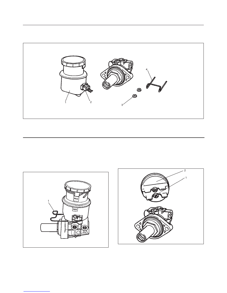
Fluid Reservoir Tank and Associated Parts
330RW003
Legend
(1) Fluid Reservoir
(2) Electrical Connector
(3) O–ring
(4) Retainer
Removal
NOTE: Before removing the fluid reservoir, remove the
brake fluid from the fluid reservoir.
1. Disconnect electrical connector.
2. Remove retainer (1).
330RW004
3. Remove fluid reservoir and the fluid level sensor built
into the fluid reservoir. The fluid level sensor cannot
be removed for servicing.
4. Remove O–ring.
Installation
To install, follow the removal steps in the reverse order,
noting the following points:
1. O–ring (1) must be set onto the fluid reservoir (2),
before installing fluid reservoir.
330RW005
5C–22 POWER–ASSISTED BRAKE SYSTEM
Master Cylinder Assembly
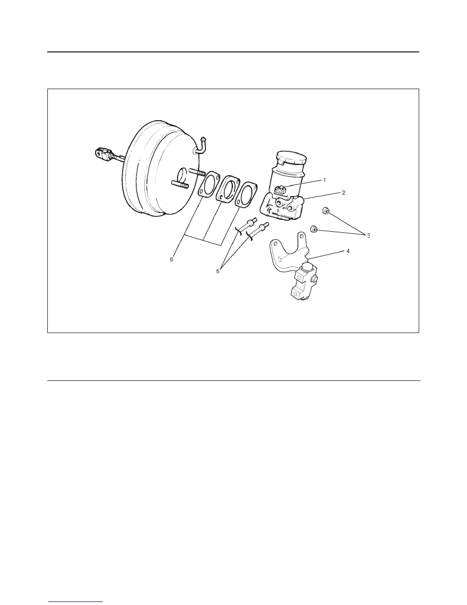
Master Cylinder Assembly and Associated Parts
330RW010
Legend
(1) Electrical Connector
(2) Master Cylinder
(3) 2 attaching Nuts
(4) P&B Valve and Bracket
(5) Brake Pipes
(6) Spacer and 2 gaskets
Removal
CAUTION: When removing the master cylinder from
the vacuum booster, be sure to get rid of the internal
negative pressure of the vacuum booster (by, for
instance, disconnecting the vacuum hose) in
advance.
If any negative pressure remains in the vacuum
booster, the piston may possibly come out when the
master cylinder is being removed, letting the brake
fluid run out.
While removing the master cylinder, further, do not
hold the piston as it can be easily pulled out.
Outside surface of the piston is the surface on which
seals are to slide. Care should be taken to keep the
surface free of cuts and dents.
1. Disconnect electrical connector.
2. Remove brake pipes and after disconnecting the
brake pipe, cap or tape the openings of the brake pipe
to prevent the entry of foreign matter.
3. Remove 2 attaching nuts.
4. Remove P&B valve and bracket.
5. Remove master cylinder.
6. Remove spacer and the 2 gaskets.
Inspection and Repair
Master Cylinder
The master cylinder is not repairable and must be
replaced as a complete assembly if found defective.
Inspection
Excessive brake pedal travel, malfunction or dragging
brake suggests that the master cylinder is defective. In
such cases perform the following visual check:
Visual Check
Make parts replacement as required if wear, distortion,
nicks, cuts, corrosion, or other abnormal conditions are
found through the following parts inspection:
f
Master cylinder body
f
Fluid reservoir
f
O–ring
5C–23
POWER–ASSISTED BRAKE SYSTEM
Functional Inspection of Master Cylinder
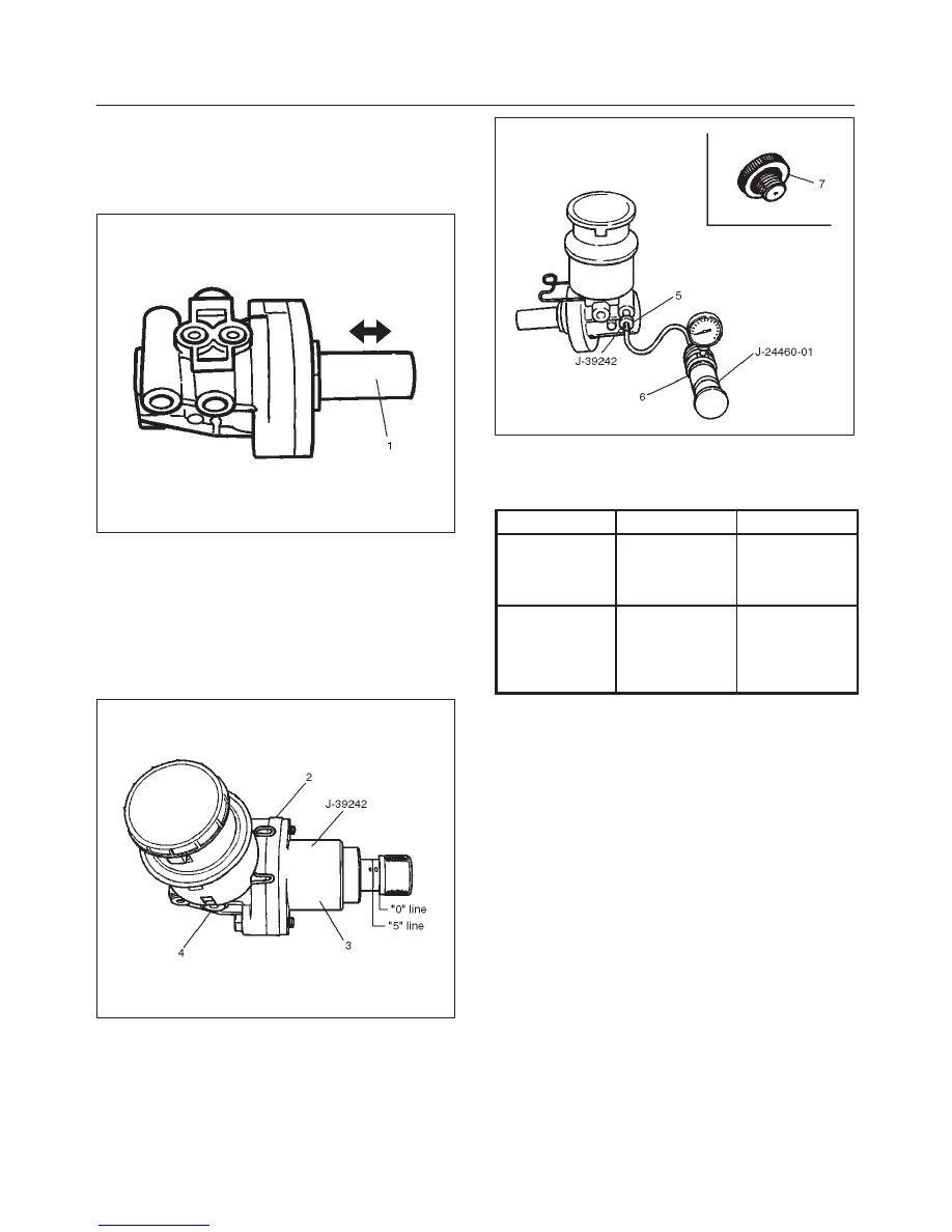
Piston
Push the primary piston (1) with your fingers to check that
it travels smoothly. If the motion is questionable, replace
the master cylinder as a complete assembly.
330RW007
Functional Inspection of Master Cylinder
Inspect the master cylinder for function as follows. If any
abnormal function is found, replace with a new one.
Install the primary piston holder (3) J–39242 (including
the master cylinder attachment (5) and master cylinder
plug (7)) onto the master cylinder (4). Make sure the
spacer (2) (2 bolts) with its adjusting bolt is screwed in up
to the “0” line
330RW008
Connect the master cylinder attachment (5) J–39242 with
the end of the radiator cap tester (6) J–24460–01, and
apply air pressure with the cap tester. Make sure there is
no rise in pressure and that with the adjusting bolt further
screwed in 5 mm (align the adjusting bolt to the “5” line).
There should be a pressure increase of 0.5 kg/cm
2
or
more.
330RW009
NOTE: When checking the front (or primary) side, be
sure to mount the master cylinder plug in the rear (or
secondary) port.
“0” Line
“5” Line
Apply air
pressure to the
front and rear
ports
No pressure
rise.
Pressure
increase of 0.5
kg/cm
2
or more
Remarks
Checks port
into the
atmospheric
pressure
chamber
Checks air
tightness of the
pressure
chamber
NOTE:
1. Do not use an air compressor, as the air from the
compressor is mixed with compressor oil.
2. When installing the master cylinder onto the vacuum
booster, always adjust the vacuum booster push rod.
(Refer to “Vacuum Booster” in this section).
3. After the master cylinder is installed onto the vehicle,
check for leakage, pedal travel and pedal free play.
Installation
1. Install spacer and the 2 gaskets.
2. Install master cylinder.
When replacing the master cylinder or vacuum
booster or both, always measure the vacuum booster
push rod protrusion and adjust it as necessary (Refer
to “Vacuum Booster” in section).
3. Install P&B valve and bracket.
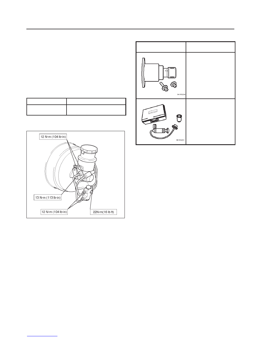
4. Install 2 attaching nuts and tighten the attaching nuts
to the specified torque.
Torque: 13 N·m (113 lb in)
5C–24 POWER–ASSISTED BRAKE SYSTEM
5. Install brake pipes and tighten the brake pipe to the
specified torque.
Master cylinder and P&B valve sides
Torque: 12 N·m (104 lb in)
Others
Torque: 16 N·m (12 lb in)
6. Connect electrical connector.
Main Data and Specifications
General Specifications
Type
Dual–circuit
Piston bore
diameter
25.4 mm (1.000 in)
Torque Specifications
E05RW016
Special Tools
ILLUSTRATION
TOOL NO.
TOOL NAME
J-39242
Primary Piston Holder
(including master
cylinder attachment and
master cylinder plug
J-24460-01
Radiator Cap Tester
Нет комментариевНе стесняйтесь поделиться с нами вашим ценным мнением.
Текст